Caphe introduction
In this guide, we introduce our circuit simulator, Caphe, used for analyzing circuits both in frequency and time domain. It allows for example to calculate the transmission of a complex photonic filter, and to simulate and analyze the response of a photonic transciever. Photonic circuits are defined in IPKISS, and are then simulated using Caphe. All information defined in IPKISS can be used during the simulation (for example, layout information, waveguide properties, and so on). During the guide we will emphasize the importance of a circuit simulator to efficiently design a photonic circuit.
Circuit simulations
There is a variety of tools available to simulate the behavior of light, using different techniques and different levels of approximations of Maxwell’s equations. For example, Finite Difference Time Domain (FDTD), Eigenmode Expansion (EME), Beam Propagation Method (BPM) (each with its advantages and disadvantages in terms of accuracy, memory and speed). Many of these tools are limited to small networks of only a handful of components, and hence their applicability for simulating or optimizing a larger photonic circuit is limited. At this point, it becomes useful to approximate each optical component as a black box. A passive and linear photonic component is then modeled by a simple scatter matrix. A nonlinear element is reduced to a time-domain equation.
This approach is visualized for a simple photonic device: a Mach-Zehnder Interferometer. As you can see, this component is constructed out of four subcomponents. Although it is fairly easy to simulate the individual components using for example FDTD (which is computationally an expensive simulator in terms of memory and time), it becomes more difficult to simulate the whole device, as the geometry becomes very large, and hence, becomes less appropriate for FDTD simulation. On the other hand, when the behavior of each individual block is correctly characterized (using a scatter matrix), it becomes possible to simulate this device very efficiently.
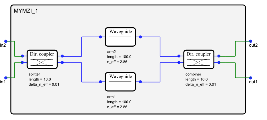
An example photonic circuit consisting of four components. The component is called a Mach-Zehnder Interferometer (MZI), which can be used as an optical filter.
The main advantage of this approach is that it becomes possible to analyze a photonic circuit, consisting of several building blocks. Each block is parametrized, and these parameters can be changed quickly for inspecting the resulting spectra or time-domain traces (for example, in the MZI above, we can quickly change the length of the arms and see how the filter adjusts). Or, the parameters can be optimized using optimization routines. As such, a circuit simulator, such as Caphe, capable of simulating this complexity, becomes indispensable in designing and optimizing optical circuits and systems.
Building blocks for circuit simulations
As previously mentioned, Caphe simulates networks of components, by dividing the network into building blocks. Each building block has a model (in time or in frequency domain or both) attached to it. These models can be either very simple analytical models that come straight from your textbook. They can also be based on simulation results obtained through the use of physical solvers such as FDTD, EME or BPM or even be based on previous measurements of a fabricated component. Usually the former models are relevant in an exploratory phase of a circuit design and the latter are used in the characterization stages.
In Caphe, the models are essentially python scripts. This means that Caphe is extremely flexible in the definition of models, which allows you to
use analytical equations in your models.
reuse the result of physical simulations in your models.
reuse the result of measurements in your models.
access all the properties that are present in your design flow. For example, these properties can define your layout or be technology specific. This avoids duplication of information making your models more robust, flexible and easier to document.
Also, you also attach different models to a single component allowing you to switching between them during the different stages of your design in a very flexible and robust way.
Running circuit simulations in IPKISS
Please follow the circuit tutorial to learn how to define and run simulations in IPKISS. The Model API reference lists the available classes and functions for defining models.
Almost all components in PICAZZO already have circuit models attached to them. This means that you can already run circuit simulations immediately if you reuse the PICAZZO library. In addition, the si_fab demonstration library that ships with the software (under the pdks/si_fab folder of your luceda-academy installation), also contains a list of circuit models that can be used as a starting point.
Advantages of using Caphe
The main advantages of using the circuit simulator Caphe are:
You have full control over what happens during the simulation. Apart from the available models, it is very easy to:
define your own S-matrix and Ordinary Differential Equations (ODEs) in pure Python and debug them during model creation,
these models can then be compiled behind the scenes to machine code for optimal speed.
It is very fast. Typical frequency sweeps (with > 10k wavelength points) of medium-sized circuits (i.e., 10-40 components) take less than a second to complete on a regular desktop computer. This is possible because of the compilation, allowing very efficient filling of the matrices, and thanks to the usage of a very efficient LU solver, optimized for circuit topologies.
Reuse of information to reduce errors in your design.
The Caphe circuit is extracted based on the netlists that are defined by IPKISS.
This netlist information can be reused in different parts of your workflow. For example, if the layout re-uses netlist information (schematic driven layout), there is an additional check that the layout and simulation describe the same circuit. Additionally, the circuit models can extract information from the layout (i.e., the length of a waveguide), again decreasing the possibility to introduce errors.
Further reading
To get acquainted with Caphe, you can read the following tutorial: Implementing circuit models in IPKISS.