The Layout View
The Layout View of a parametric cell defines the drawings which are needed to obtain masks for fabrication of the IC. A typical layout may consist of several types of drawing elements for different purposes:
Geometric elements which relate to functional elements on a chip, e.g. waveguide, active area
Auxiliary geometric elements which are used to generate the actual drawings on the mask, e.g. inversion layers
Geometric elements which are used for generation of data on the mask, e.g. clear-out regions for dummy filling
Text or graphical elements such as logos, which will appear on the chip, for documentation purposes
Auxiliary geometric elements and text label annotations which do not appear on the actual mask/chip but are used to indicate devices and pins to a person or a software tool inspecting the layout (e.g. for extraction and verification)
In addition to these elements, a Layout View of a cell can contain further information and components:
Layout references to (the layout view of) other cells, implementing hierarchy (see Hierarchical PCells)
Information about the input and output ports (physical interfaces to the world outside a cell)
Layout concepts
There are several concepts we need to get familiar with before defining a layout. These have to do with the different types of information that all have to be represented on a basically two-dimensional computer screen or print.
Layers: every geometric element is drawn on a certain layer. A layer typically corresponds to a type of functional element or a process module: waveguide core, fiber coupler grating, AR coating on a facet, metal wire, … A layer is given a color and fill scheme in a visualisation tool
Drawing purpose: every geometric element is also associated with a specific purpose or data type. The purpose expresses what the use of the element is, relative to a specific Layer. Hence, every geometric element is in fact written on a certain (Layer, Purpose) combination. As with layers, purposes are given color or fill style variations in a visualisation tool. Examples of purposes include drawing (for mask elements), pin (for pin recognition) and so forth.
Element: a geometric element, drawn on a certain layer-purpose pair.
Reference or Instance: a type of element refering to another PCell.
Port: the physical implementation of a terminal, the interface of a component to other components or to IC interfaces. Contains information about physical properties, such as waveguide template, position and outward pointing angle of the interface, etc. A port is often represented on the layout using a pin recognition layer (PINREC)
Defining the layout view
In IPKISS you define the layout view of a PCell by defining a subclass of LayoutView:
import ipkiss3.all as i3

class RectangleCell(i3.PCell):
    """ This defines the RectangleCell PCell
    """

    _name_prefix = 'RECTCELL'

    width = i3.PositiveNumberProperty(default=1.0)
    height = i3.PositiveNumberProperty(default=2.0)

    class Layout(i3.LayoutView):
        """This is the layout view of RectangleCell
        """

        # these are view specific properties:
        layer = i3.LayerProperty(default=i3.TECH.TRACE.DEFAULT_LAYER)

        def _generate_elements(self, elems):
            elems += i3.Rectangle(layer=self.layer, box_size=(self.width, self.height))
            return elems

        def _generate_ports(self, ports):
            ports += i3.OpticalPort(position=(-0.5*self.width, 0.0), angle=180.0)
            return ports
Some of the main concepts can be recognized in this example: use of a layer to draw a Rectangle element, and definition of an optical Port with a position and an angle.
Shapes
Ipkiss separates the geometrical content of an element from its other properties like the layer on which it is drawn, or its type.
The basic container for a geometrical object is a Shape (i3.Shape). Shapes can be operated on: they can be added to each
other, their direction can be swapped, they can be transformed, and information about their size can be retrieved.
Ipkiss defines a range of higher-level shapes such as Circle, Rectangle, Arc, and so on. Each of these could be exported to corresponding primitives in data exchange files. Each of them can also be discretized to a set of points in a two-dimensional Carthesian plance, hence becoming a polygon. Therefore they can always be exported to file formats which do not support these higher level shapes, such as GDSII, or their points can be used by the designer to do specific calculations.
In the reference manual you can find Geometry Reference.
The very basic Shape is just a collection of points (a list of i3.Coord2 objects). Let’s make a simple layout with such a generic Shape:
class Enterprise(i3.PCell):
    class Layout(i3.LayoutView):
        def _generate_elements(self, elems):
            coordinates = i3.Shape([(-179,54), (101,54), (101,149), (59,149), (-11,172), (-39,209),
                                    (-11,246), (59,268), (696,268), (768,246), (795,209), (768,172),
                                    (696,149), (147,149), (147,54), (186,54), (238,31), (258,-5),
                                    (238,-42), (186,-65), (147,-65), (147,-139), (696,-139),
                                    (768,-161), (795,-198), (768,-235), (696,-258), (59,-258),
                                    (-11,-235), (-39,-198), (-11,-161), (59,-139), (101,-139),
                                    (101,-65), (-179,-65), (-179,-100), (-297,-262), (-487,-323),
                                    (-678,-262), (-795,-100), (-795,100), (-678,262), (-487,323),
                                    (-297,262), (-179,100)],
                                    closed = True
                                    )
            coordinates.magnify((0.0, 0.0), 0.1)
            coordinates.rotate((0.0, 0.0), -45.0)
            coordinates.move((100, 0))
            elems += i3.Boundary(layer=i3.Layer(0), shape=coordinates)
            return elems
Using the visualize command, we can see our layout on screen, and using the write_gdsii command, we can export to GDSII:
enterprise = Enterprise(name="enterprise")
layout = enterprise.get_default_view(i3.LayoutView)
layout.write_gdsii("enterprise.gds")
layout.visualize()
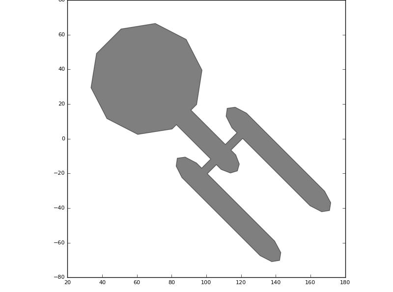
A simple Shape example
For a more in-depth introduction, see the guide on Shapes.
Elements
In the example above, we already used i3.Boundary to create a polygon. There are in fact several basic types of elements:
Boundary is an element which can be exported to a polygon. It is a filled Shape on a given layer.
Path is used for wires - a Shape defines its centerline, it has a given with along that centerline, and is drawn on a given layer
Reference element is used to refer to (the layout view of) another PCell. Several types of reference elements are available for single and array references
PolygonText draws text on the mask on a given layer, which will appear on the chip.
Label is a text element which is used to annotate the design - it is drawn on a given layer but will not appear on the actual mask
Ipkiss predefines a variety of Boundary and Path elements, an overview of which can be found in Elements and Layers.
Wedge, ParabolicWegde, Circle, Ellipse, Rectangle, RoundedRectangle, Box, RegularPolygon,…
Line, CirclePath, EllipsePath, RectanglePath, …
Boundary and Path elements
The following example illustrates the difference between Boundary and Path elements, using rectangle-based elements:
class Layout(i3.LayoutView):
     def _generate_elements(self, elems):
          #filled rectangle using Rectangle
          elems += i3.Rectangle(layer=i3. Layer(0),
                                center=(0,0),
                                box_size=(50, 30))
          #rectangular line
          elems += i3.RectanglePath(layer=i3.Layer(0),
                                    center=(100,0),
                                    box_size=(50, 30),
                                    line_width=2.0)
          #filled round rectangle using RoundedRectangle
          elems += i3.RoundedRectangle(layer=i3.Layer(0),
                                       center=(0, 50),
                                       box_size=(50, 30),
                                       radius=3.0)
          #rounded rectangular line
          elems += i3.RoundedRectanglePath(layer=i3.Layer(0),
                                           center=(100, 50),
                                           box_size=(50, 30),
                                           radius=3.0,
                                           line_width=2.0)
          return elems
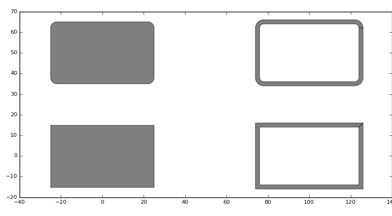
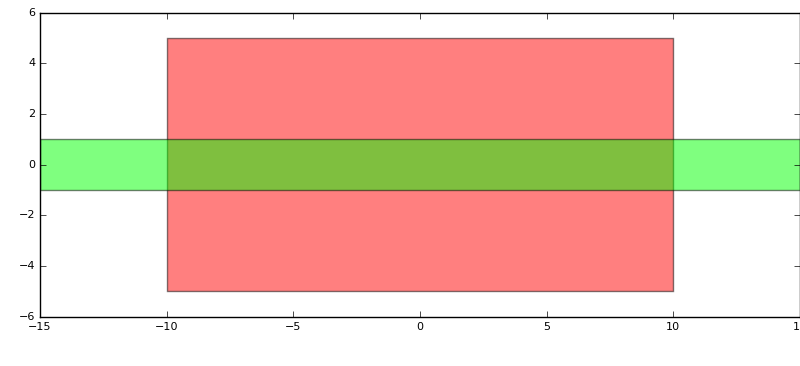
A Rectangle, RectanglePath, RoundedRectangle and RoundedRectanglePath
There are many more pre-defined Boundary and Path elements.
PolygonText
You can use the i3.PolygonText element to add text on the design on a drawing layer. Let’s add some text to the Enterprise shape we defined earlier:
class Enterprise(i3.PCell):
    class Layout(i3.LayoutView):
        def _generate_elements(self, elems):
            coordinates = i3.Shape([(-179,54), (101,54), (101,149), (59,149), (-11,172), (-39,209),
                                    (-11,246), (59,268), (696,268), (768,246), (795,209), (768,172),
                                    (696,149), (147,149), (147,54), (186,54), (238,31), (258,-5),
                                    (238,-42), (186,-65), (147,-65), (147,-139), (696,-139),
                                    (768,-161), (795,-198), (768,-235), (696,-258), (59,-258),
                                    (-11,-235), (-39,-198), (-11,-161), (59,-139), (101,-139),
                                    (101,-65), (-179,-65), (-179,-100), (-297,-262), (-487,-323),
                                    (-678,-262), (-795,-100), (-795,100), (-678,262), (-487,323),
                                    (-297,262), (-179,100)],
                                   closed = True
                               )
            coordinates.magnify((0.0, 0.0), 0.1)
            coordinates.rotate((0.0, 0.0), -45.0)
            coordinates.move((100, 0))
            elems += i3.Boundary(layer=i3.Layer(0), shape=coordinates)

            elems += i3.PolygonText (layer=i3.Layer(1),
                                     coordinate=(70.0,100.0),
                                     text="Welcome to the Enterprise",
                                     alignment=(i3.TEXT.ALIGN.CENTER, i3.TEXT.ALIGN.TOP),
                                     font=i3.TEXT.FONT.DEFAULT,
                                     height=8,
                                     transformation=i3.Rotation((0.0, 0.0), 5.0))
            return elems
The PolygonText element takes several parameters, including the coordinate where to put the text, the alignment (horizontal and vertical) to the coordinate, the font to use and the font height. In this example we rotate the text by 5 degrees.
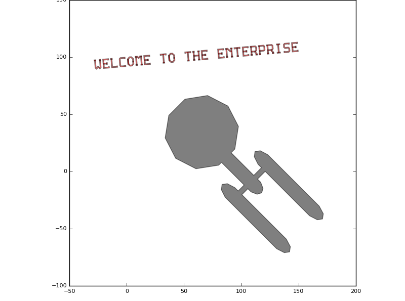
Use of PolygonText
Groups
For convenience of handling, Elements can be grouped in a logical container i3.Group. The group of elements can be jointly operated on, like for transformations or
retrieving size information
Again, this is best illustrated with an example:
class GroupExample(i3.PCell):
    class Layout(i3.LayoutView):
        def _generate_elements(self, elems):

            # create a group consisting of a rectangle and an ellipse
            my_group = i3.Group()
            my_group += i3.Rectangle(layer=i3.Layer(1),
                                     box_size=(20.0,30.0),
                                     center=(0.0,0.0))
            my_group += i3.Ellipse(layer=i3.Layer(2),
                                   box_size=(40.0,15.0))
            # rotate the group by 30 degrees
            my_group.transform(i3.Rotation(rotation=30.0))

            elems += my_group

            # retrieve the bounding box of the group and add a rectangle around it:
            # take the convex hull of the group, retrieve its bounding box,
            # and grow it with half the line width of our rectangle
            bbox_shape = my_group.convex_hull().size_info.bounding_box
            elems += i3.Path(layer=i3.Layer(3),
                             shape= i3.ShapeGrow(original_shape=bbox_shape, amount=1.0),
                             line_width=2.0
                             )
            # Let's plot the convex hull as well, so you see what we do:
            elems += i3.Path(layer=i3.Layer(4),
                             shape=my_group.convex_hull(),
                             line_width=0.1)
            return elems
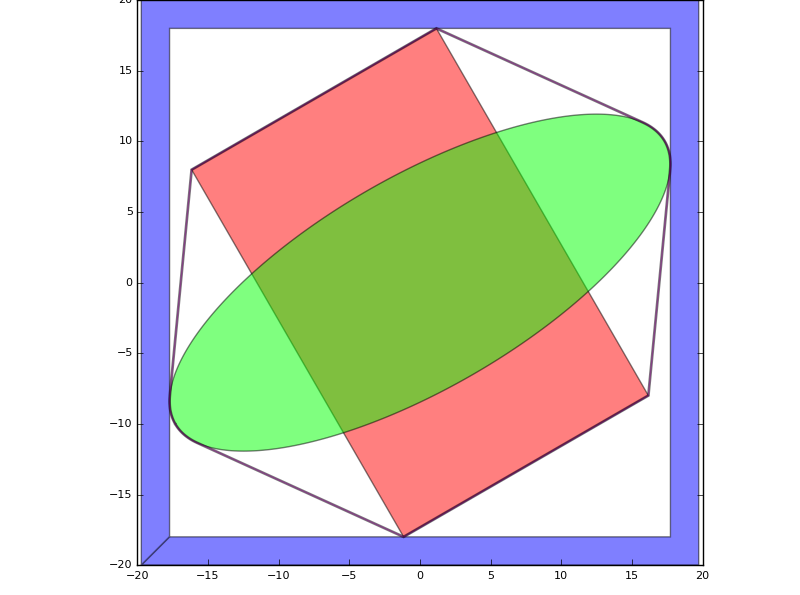
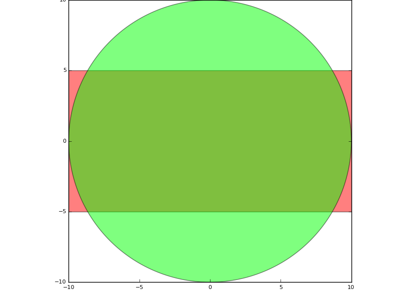
Use of Group, convex hull and size_info
Using shape operations
As already mentioned, shapes can be added, reversed and otherwise operated on. Let’s define a parametric cell which represents some kind of 1:2 splitter to illustrate:
class WeirdSplitter(i3.PCell):

    class Layout(i3.LayoutView):
        port_width = i3.PositiveNumberProperty(default=0.5)

        def _generate_elements(self, elems):
            s_upper = i3.Shape([(0.0,0.5*self.port_width),
                                (3.0,0.5*self.port_width+0.4),
                                (4.0,0.5*self.port_width+1.2),
                                (8.0,0.5*self.port_width+3.0),
                                (8.0,0.5*self.port_width+3.0-self.port_width),
                                (6.0,0.5*self.port_width+1.0-self.port_width),
                                (6.0,0.0)])
            s_lower = s_upper.v_mirror_copy()
            s_total = s_upper + s_lower.reversed()
            elems += i3.Boundary(layer=i3.Layer(1), shape=s_total)
            return elems
This is another example of how to effectively use shapes: to create a symmetric element in this example, we first define the upper (northern) part of the shape. Then we do a mirror copy to generate the lower part of the shape, and adding the two together yields the complete shape of our splitter.
The result is shown below:
w = WeirdSplitter()
l = w.Layout(port_width=0.5)
l.visualize()
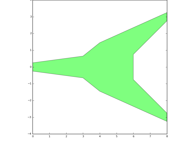
Use of shape operations to generate a component
Working with process purpose layers
Until now, we have been using Layer() as a construct to indicate the layer on which to draw. That’s ok for simple layouts, but doesn’t tell much about the link to the process and doesn’t allow to split between different drawing purposes. As we already discussed,
a drawing layer usually relates to a function or specific structure in the technology, like active area, gate poly, contact plug, metal wire, waveguide, shallow etched grating, heater, …
a drawing purpose usually relates to how an element should be interpreted, like being an actual part of the drawn mask, a pin recognition layer, an invisible text label, etc.
Elements could be drawn on the same layer with different drawing purposes. The technology file will define which are the valid layers, valid drawing
purposes, and which are the valid layer-purpose combinations. In Ipkiss, we define layer-purpose combinations using i3.PPLayer.
In the following example we rewrite our WeirdSplitter example and now draw the shape of the splitter on the si_fab PDK’s PPLayer TECH.PPLAYER.SI. We add pin recognition layers as well, on PPLayer TECH.PPLAYER.PINREC. The first elements will be visible on the mask (chip), whereas the pin recognition layers will be in the mask file, but not on the chip - they are used for verification, visualisation and automation.
class WeirdSplitter(i3.PCell):

    class Layout(i3.LayoutView):
        port_width = i3.PositiveNumberProperty(default=0.5)

        def _generate_elements(self, elems):
            s_upper = i3.Shape([(0.0,0.5*self.port_width),
                                (3.0,0.5*self.port_width+0.4),
                                (4.0,0.5*self.port_width+1.2),
                                (8.0,0.5*self.port_width+3.0),
                                (8.0,0.5*self.port_width+3.0-self.port_width),
                                (6.0,0.5*self.port_width+1.0-self.port_width),
                                (6.0,0.0)])
            s_lower = s_upper.v_mirror_copy()
            s_total = s_upper + s_lower.reversed()
            elems += i3.Boundary(layer=i3.PPLayer(TECH.PROCESS.WG, TECH.PURPOSE.LF.LINE), shape=s_total)

            pin_rect = i3.ShapeRectangle(box_size=(self.port_width,self.port_width))
            east_port_y = 0.5*self.port_width+3.0-0.5*self.port_width
            elems += i3.Boundary(layer=i3.PPLayer(TECH.PROCESS.WG, TECH.PURPOSE.PIN), shape=pin_rect)
            elems += i3.Boundary(layer=i3.PPLayer(TECH.PROCESS.WG, TECH.PURPOSE.PIN), shape=pin_rect.move_copy((8.0,east_port_y)))
            elems += i3.Boundary(layer=i3.PPLayer(TECH.PROCESS.WG, TECH.PURPOSE.PIN), shape=pin_rect.move_copy((8.0,-east_port_y)))

            return elems
For further information, see the technology guide.
Defining ports
When you are happy with the layout elements of a device, you can also add the information about its input and output ports. In this guide, we will just cover a generic example. For actual optical devices, see the guide on using waveguides.
Returning to our weird splitter example:
class WeirdSplitter(i3.PCell):
    class Layout(i3.LayoutView):
        def _generate_elements(self, elems):
            ...
            return elems

        def _generate_ports(self, ports):
            ports += i3.OpticalPort(name="in", position=(0.0,0.0), angle=180.0)
            ports += i3.OpticalPort(name="out1", position=(8.0,3.0), angle=0.0)
            ports += i3.OpticalPort(name="out2", position=(8.0,-3.0), angle=0.0)
            return ports
The above code adds three ports to the device, at given positions and with a specified outwards facing angle, as illustrated by the following figure:
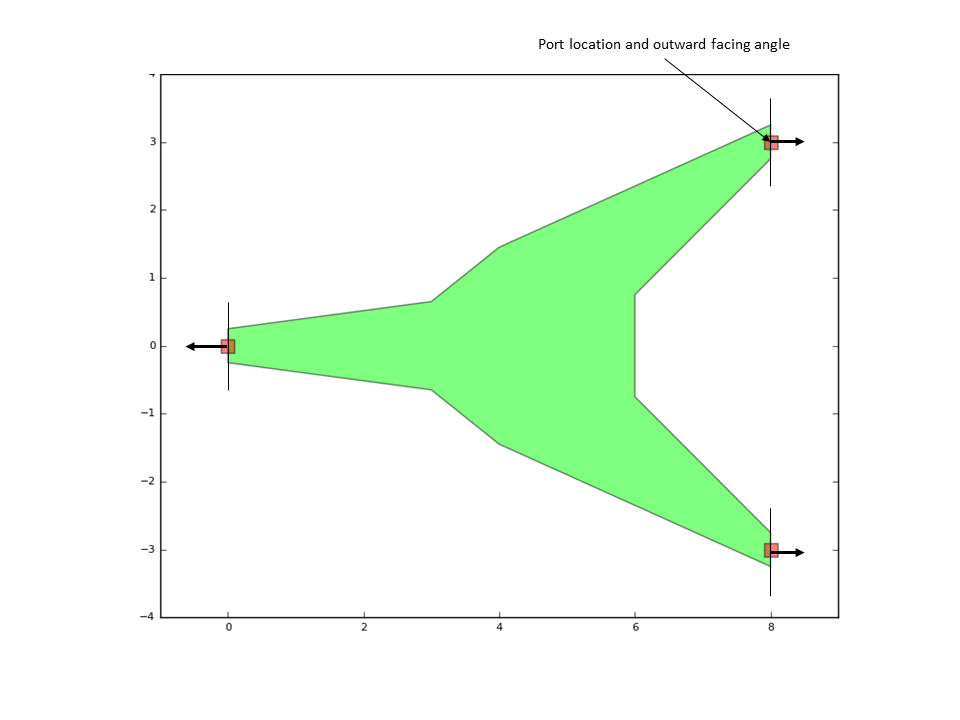
Definition of port location and angle
Adding instances
To illustrate how to add instances of other PCells to a device, and illustrate the use of ports in the meantime, let’s create a new PCell which will take any other PCell’s layout and plot a rectangle at every port location:
class PrintPorts(i3.PCell):
    original_cell = i3.ChildCellProperty()

    class Layout(i3.LayoutView):
        def _generate_instances(self, insts):
            insts += i3.SRef(reference=self.original_cell, name="original")
            return insts

        def _generate_elements(self, elems):
            for p in self.original_cell.ports:
                elems += i3.Rectangle(layer=i3.PPLayer(TECH.PROCESS.WG, TECH.PURPOSE.PIN), center=p.position,
                                      box_size = (0.2,0.2))
            return elems

w = WeirdSplitter(port_width=0.5)
w_ports = PrintPorts(original_cell=w)
w_ports.Layout.view.visualize()
w_ports.Layout.view.write_gdsii("weird_splitter_ports.gds")
Here, we used a ChildCellProperty to pass a child PCell as a property to the parent pcell.
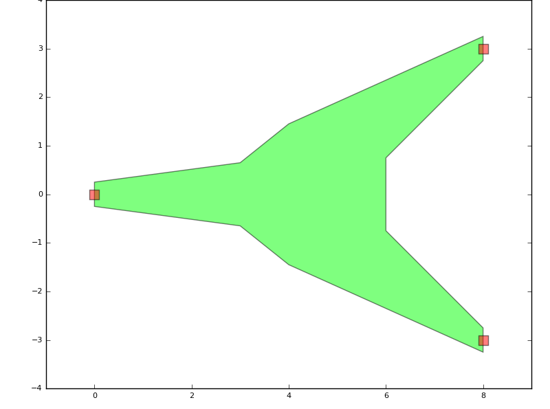
Example of using instances and ports
In the resulting GDSII file, you can notice the hierarchy in the design: the top level cell has the small squares at the port locations, as well as an instance to the WeirdSplitter cell.
Layout view inheritance
As with any other Views, inheritance can be used to maximize re-use of code when constructing Layout Views of PCells which have a lot in common. A PCell and its views can inherit from a base class which provides more basic or common functionality.
Let’s illustrate this with an example of two PCells: one consisting of a rectangle and a circle, one consisting of rectangle and an line. The common component is a rectangle, so we define a base class first:
class RectangleCell(i3.PCell):

    class Layout(i3.LayoutView):

        box_size = i3.Size2Property(default=(20,10))

        def _generate_elements(self, elems):
            elems += i3.Rectangle(layer=i3.Layer(1),
                                  box_size=self.box_size)
            return elems
The, we derive the two child classes:
class RectWithCircle(RectangleCell):
    class Layout(RectangleCell.Layout):
        radius = i3.PositiveNumberProperty(default=10.0)
        def _generate_elements(self, elems):
            super(RectWithCircle.Layout, self)._generate_elements(elems)
            elems += i3.Circle(layer=i3.Layer(2),
                               radius=self.radius)
            return elems

class RectWithLine(RectangleCell):
    class Layout(RectangleCell.Layout):
        line_width = i3.PositiveNumberProperty(default=2.0)
        def _generate_elements(self, elems):
            super(RectWithLine.Layout, self)._generate_elements(elems)
            elems += i3.Line(layer=i3.Layer(2),
                             begin_coord=(-0.75*self.box_size[0],0.0),
                             end_coord=(0.75*self.box_size[0],0.0),
                             line_width=self.line_width)
            return elems

R1 = RectWithCircle().Layout()
R1.visualize()
R2 = RectWithLine().Layout()
R2.visualize()
Note the use of super(class, self) in order to call the _generate_elements of the superclass, so we can just add new elements to it. Make sure to write super(RectWithLine.Layout, self)._generate_elements(elems), not super(Layout, self)._generate_elements(elems).
The result is:
Example of using inheritance: rectangle with circle
Example of using inheritance: rectangle with line