Boolean Operations
Boolean operations can be executed on three types of objects: Shapes, Elements and Layers. Standard Python operators can be used.
The following operations are supported:
Boolean |
Operator |
Description |
Supported objects |
|---|---|---|---|
a AND b |
& |
Intersection (conjunction) |
Shape, Element, Layer |
a OR b |
| |
Union (disjunction) |
Shape, Element, Layer |
a XOR b |
^ |
Exclusive disjunction |
Shape, Element, Layer |
a NOT b |
- |
Difference |
Shape, Element, Layer |
NOT a |
~ |
(Unary) Negation |
Layer |
Note
Boolean operations do exactly that: boolean operations. They do not guarantee that the result can be processed by other software tools or can be manufactured. E.g. booleans may generate polygons with coinciding vertices or touching edges, which are not valid in all tools or in all geometrical operations.
Booleans between Shapes
Binary boolean operations can be used between any two Shape objects.
The result is a list of shapes.
As an example, let’s perform AND, OR, XOR and NOT on two rectangle shapes:
shape_rect_1 = i3.ShapeRectangle(center=(20.0, 10.0), box_size=(20.0, 20.0))
shape_rect_2 = i3.ShapeRectangle(center=(30.0, 20.0), box_size=(10.0, 10.0))
Using the standard python operators you can generate the binary boolean AND, OR, XOR and NOT operations:
shapes_and = shape_rect_1 & shape_rect_2
shapes_or = shape_rect_1 | shape_rect_2
shapes_xor = shape_rect_1 ^ shape_rect_2
shapes_not = shape_rect_1 - shape_rect_2
We can now visualize the result by plotting the coordinates with matplotlib:
def plot_shapes(subplotnr, shapes, title=""):
    # helper function to plot shapes in a subplot
    axes = plt.subplot(subplotnr)
    for shape in shapes:
        x = list(shape.x_coords())
        y = list(shape.y_coords())
        x.append(x[0])  # close shape
        y.append(y[0])
        axes.plot(x, y, "o-", markersize=7, linewidth=2)
    axes.set_aspect("equal")
    axes.set_xlim([0.0, 40.0])
    axes.set_ylim([-10.0, 30.0])
    axes.set_title(title)


plt.figure()
plot_shapes(151, [shape_rect_1, shape_rect_2], "original")
plot_shapes(152, shapes_and, "AND")
plot_shapes(153, shapes_or, "OR")
plot_shapes(154, shapes_xor, "XOR")
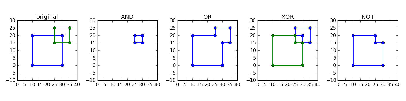
Schematic representation of different boolean operations.
An alternative is to use the resulting shapes to create layout elements and visualize those.
First, we use the shape to create boundary (polygon) elements:
# 4. make boundaries (polygons) for each of the results
bnd_and = [i3.Boundary(layer=i3.Layer(0), shape=shape) for shape in shapes_and]
bnd_or = [i3.Boundary(layer=i3.Layer(0), shape=shape) for shape in shapes_or]
Then, we create a cell for the original and each boolean result and a master cell which groups all of them:
# 5. make a layout with the shapes so we can visualize it and save to GDSII
layout_original = i3.LayoutCell(name="original").Layout(
    elements=[i3.Boundary(layer=i3.Layer(0), shape=shape_rect_1), i3.Boundary(layer=i3.Layer(0), shape=shape_rect_2)]
)

layout_and = i3.LayoutCell(name="AND").Layout(elements=bnd_and)
layout_or = i3.LayoutCell(name="OR").Layout(elements=bnd_or)
layout_xor = i3.LayoutCell(name="XOR").Layout(elements=bnd_xor)
layout_not = i3.LayoutCell(name="NOT").Layout(elements=bnd_not)

layout = i3.LayoutCell(name="boolean_ops_shape").Layout(
    elements=[
        i3.SRef(layout_original, (0.0, 0.0)),
        i3.SRef(layout_and, (50.0, 0.0)),
        i3.SRef(layout_or, (100.0, 0.0)),
        i3.SRef(layout_xor, (150.0, 0.0)),
Finally, we can save the result to GDSII and visualize it:
)
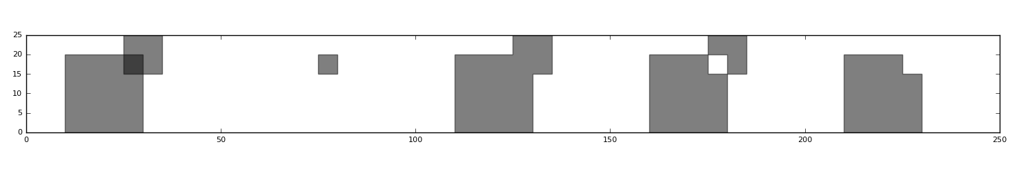
Output of different boolean operations
You can download the full example here.
Booleans between Elements
Binary boolean operations can be used between any two Boundary
or Path objects which have the same layer.
The result is a list of new Boundary objects.
Note
Careful! The boolean operation between two elements on a different layer will return an empty list (XOR, AND) or the first element only (NOT) or both elements (OR), since the operation cannot be executed.
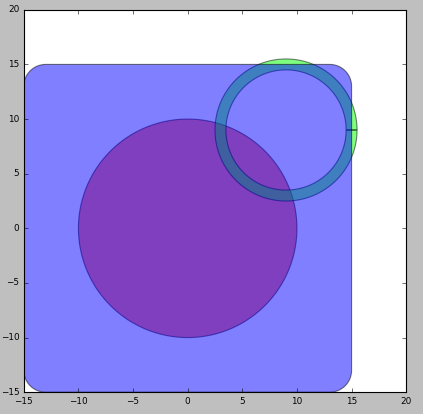
As an example, let’s perform AND, OR, XOR and NOT between an circle and a rounded rectangle:
circle = i3.Circle(layer=i3.Layer(1), center=(0.0, 0.0), radius=10.0)
rectangle = i3.RoundedRectangle(layer=i3.Layer(1), center=(8.0, 7.0), box_size=(12.0, 8.0), radius=1.0)
Using the standard python operators you can generate the binary boolean AND, OR, XOR and NOT operations:
elems_and = circle & rectangle
elems_or = circle | rectangle
elems_xor = circle ^ rectangle
elems_not = circle - rectangle
Now we can make a layout of the original and the resulting elements:
layout_original = i3.LayoutCell(name="original").Layout(elements=[circle, rectangle])
layout_and = i3.LayoutCell(name="AND").Layout(elements=elems_and)
layout_or = i3.LayoutCell(name="OR").Layout(elements=elems_or)
layout_xor = i3.LayoutCell(name="XOR").Layout(elements=elems_xor)
layout_not = i3.LayoutCell(name="NOT").Layout(elements=elems_not)

layout = i3.LayoutCell(name="boolean_ops_shape").Layout(
    elements=[
        i3.SRef(layout_original, (0.0, 0.0)),
        i3.SRef(layout_and, (50.0, 0.0)),
        i3.SRef(layout_or, (100.0, 0.0)),
        i3.SRef(layout_xor, (150.0, 0.0)),
        i3.SRef(layout_not, (200.0, 0.0)),
And visualize and save the result go GDSII:
# 4. Write to GDSII and visualize
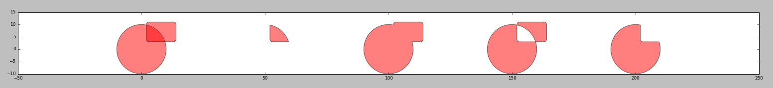
Original elements (left) and results after booleans (from left to right: AND, OR, XOR, NOT)
You can download the full example here.
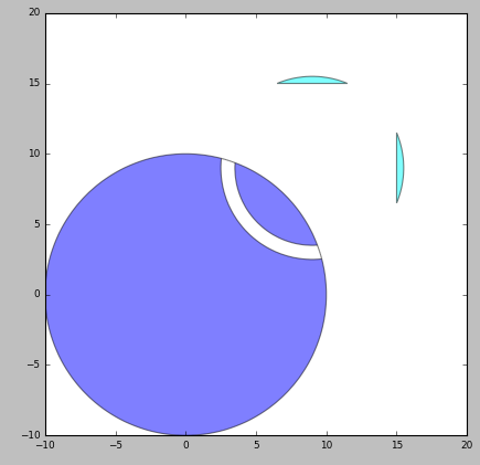
Operations including Paths
Path elements will be converted to a Boundary before executing the boolean operation.
For instance, consider the following:
circle_path = i3.CirclePath(layer=i3.Layer(1), center=(9.0, 9.0), radius=6.0, line_width=1.0)
elems_and = circle & circle_path
elems_or = circle | circle_path
elems_xor = circle ^ circle_path
elems_not = circle - circle_path
The circle_path will internally first be converted into a Boundary before applying the boolean operation. The original circle_path is untouched.
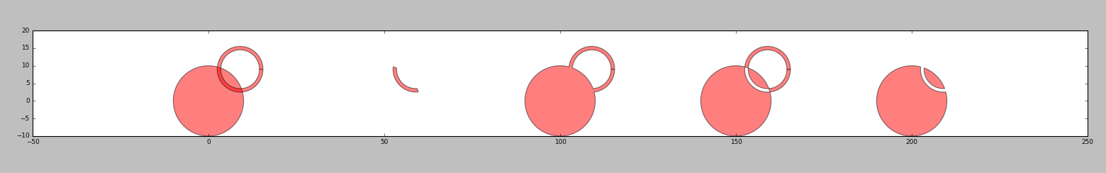
Booleans between a Boundary and a Path
You can download the full example here.
Booleans between Layers
Boolean operations between Layer objects generate Generated Layer objects which represent the composite (generated) layer. As such, the generated layer does not hold any layout information. The generated layers can be used to:
Define a virtual fabrication flow (
VFabricationProcessFlow), see Virtual Fabrication.Manually generate the elements on the generated layers (see next paragraph).
For instance, we could define two layers and generate their boolean composition:
layer1 = i3.Layer(1)
layer2 = i3.Layer(2)

layer3 = layer1 & layer2
layer4 = layer1 | layer2
layer5 = layer1 ^ layer2
layer6 = layer1 - layer2
layer7 = ~layer1
The output of this is:
(LAYER1 AND LAYER2) is a <class 'ipkiss.primitives.layer.__GeneratedLayerAnd__'>
(LAYER1 OR LAYER2) is a <class 'ipkiss.primitives.layer.__GeneratedLayerOr__'>
(LAYER1 XOR LAYER2) is a <class 'ipkiss.primitives.layer.__GeneratedLayerXor__'>
(LAYER1 SUB LAYER2) is a <class 'ipkiss.primitives.layer.__GeneratedLayerSub__'>
(NOT LAYER1) is a <class 'ipkiss.primitives.layer.__GeneratedLayerNot__'>
Generated layers can in their turn be used for generating more complex generated layers:
layer8 = (layer1 ^ layer2) & layer1
print("{} is a {}".format(layer8, type(layer8)))
With the resulting output:
((LAYER1 XOR LAYER2) AND LAYER1) is a <class 'ipkiss.primitives.layer.__GeneratedLayerAnd__'>
You can download the full example here.
Booleans between ElementLists
Once you have defined generated layers, The low-level function get_elements_for_generated_layers allows you to do map a list of elements onto an output list
of elements as they go through a set of specified boolean operations between layers. This function is used internally in the
virtual fabrication flow, but can also be used by the user to set up a fabrication mask generation flow.
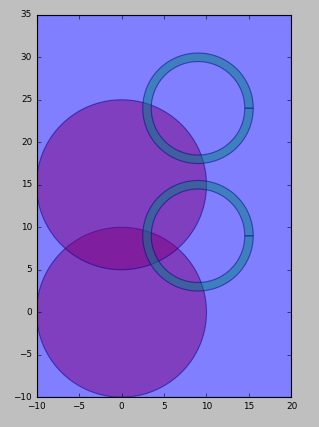
Consider the following example.
First we define the original (“drawn”) layers and a layout on these layers:
# drawn layers
layer1 = i3.Layer(1)
layer2 = i3.Layer(2)
layer3 = i3.Layer(3)

# original layout
rect = i3.RoundedRectangle(layer=layer3, center=(0.0, 0.0), box_size=(30.0, 30.0), radius=2.0)
circle = i3.Circle(layer=layer1, center=(0.0, 0.0), radius=10.0)
circle_path = i3.CirclePath(layer=layer2, center=(9.0, 9.0), radius=6.0, line_width=1.0)

layout = i3.LayoutCell(name="original").Layout(elements=[rect, circle, circle_path])
layout.visualize()
Which generates the following layout visualization:
Example layout as input for generated layers.
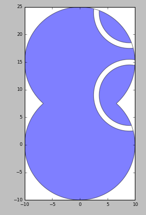
We can now define the generated layers and the output layer to which we want each generated layer to be written:
generated1 = (layer1 ^ layer2) & layer1
generated2 = ~layer3
mapping = {generated1: i3.Layer(10), generated2: i3.Layer(20)}

# generated layout
Now we can take the original elements and this mapping and use get_elements_for_generated_layers to
generate the elements on the generated layers:
final_layout.visualize()

# create and visualize a hierarchical layout
This results in the following output. On one layer (layer 10) we get the result of the circle minus the circle path (generated1). On a second layer (layer 20) we get the result of the inverse of layer3, which are only two slivers from the circle path. In order to take that inverse, the extent of the full layout is taken and then the shapes on layer 3 (in this case the rounded rectangle) are subtracted.
Resulting layout after boolean operations specified by generated layers.
This also works on hierarchical layouts, but beware that a flat copy will be taken before executing the booleans. Therefore this will not scale well to large layouts.
# create and visualize a hierarchical layout
simple_layout = i3.LayoutCell(name="circle_and_path").Layout(elements=[circle, circle_path])
top_layout = i3.LayoutCell(name="top_original").Layout(
    elements=[
        i3.SRef(simple_layout, (0.0, 0.0)),
        i3.SRef(simple_layout, (0.0, 15.0)),
        # cover the full layout with layer3
        i3.Boundary(layer=layer3, shape=[(-10.0, -10.0), (-10.0, 35.0), (20.0, 35.0), (20.0, -10.0)]),
    ]
)

top_layout.visualize()

# and create and visualize the generated result
top_output_elems = i3.get_elements_for_generated_layers(top_layout.layout, mapping)
final_top_layout = i3.LayoutCell(name="top_generated").Layout(elements=top_output_elems)
final_top_layout.visualize()
A simple hierarchical layout (two overlapping cells)
Result from hierarchical boolean operations specified by generated layers
You can download the full example here.
In case you want to merge elements on the same layer together, for example to resolve DRC errors, you can use i3.merge_elements.
This is a convenience wrapper around the get_elements_for_generated_layers.
A real-world example
Applying the above to a photonic device example, we generate the mask layout for a ring resonator in which the waveguide is defined by trenches etched next to the waveguide core. The designer draws the waveguide core as well as the extent of the cladding around it. From the mask making boolean formula, we generate the final mask drawing.
You can download the full example here.
We start by importing the silicon_photonics technology so we can use components from the Picazzo library.
import si_fab.all as pdk  # noqa
from ipkiss.technology import get_technology
import ipkiss3.all as i3
from picazzo3.traces.wire_wg.transitions import WireWaveguideTemplate
from picazzo3.filters.ring import RingRectSymm180DropFilter
from ipkiss.boolean_ops.boolean_ops_elements import get_elements_for_generated_layers
Then we define the process layers, purposes and drawing layers:
TECH = get_technology()
# process layers and purposes
wg_process = i3.ProcessLayer("waveguide", "WG")
core_purpose = i3.PatternPurpose("waveguide core", "CORE")
clad_purpose = i3.PatternPurpose("waveguide cladding", "CLAD")
Finally the mask boolean is specified:
wg_clad = i3.PPLayer(wg_process, clad_purpose, "WG_CLAD")
Now let’s create a ring resonator component. First we define the waveguide template. Picazzo has a :py:class:``WireWaveguideTemplate<picazzo3.traces.wire_wg.WireWaveguideTemplate> which can be used for this purpose. It draws a waveguide core and a surrounding cladding, for which we use the layers defined above.
# waveguide template
wg_tmpl = WireWaveguideTemplate()
wg_tmpl.Layout(
    core_width=0.5,
    cladding_width=4.5,
    core_process=wg_process,
Then we use :py:class:``RingRectSymm180DropFilter<picazzo3.filters.ring.cell.RingRectSymm180DropFilter> to define a ring resonator based on the defined waveguide template:
    cladding_purpose=clad_purpose,
)

# ring resonator
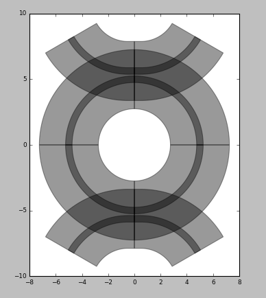
Ring resonator layout
Now we can derive the generated mask layer corresponding to this layout drawing:
ring_lo.visualize()

# use as a generated mask layer
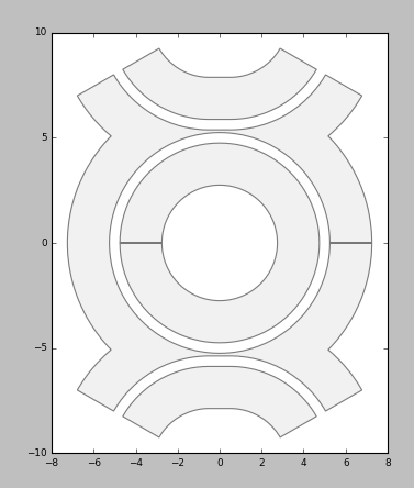
Generated mask layer
We can also use the generated layer to define a virtual fabrication flow, re-using the material stacks defined in the silicon_photonics technology.
generated_layout.visualize()

# define a virtual fabrication flow, using the material stacks in the si_fab technology
vfab_process = VFabricationProcessFlow(
    active_processes=[wg_process],
    process_layer_map={wg_process: wg_mask},
    is_lf_fabrication={wg_process: False},
Using this VFabricationProcessFlow we can now
generate the top-down and cross-section views of the resulting materials:
        ((1,), TECH.MATERIAL_STACKS.MSTACK_SOI_RIB),
    ],
)
# visualize the result of the virtual fabrication
# top-down
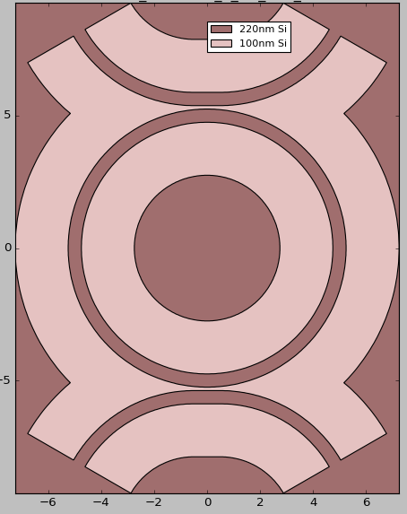
Top-down virtual fabrication view
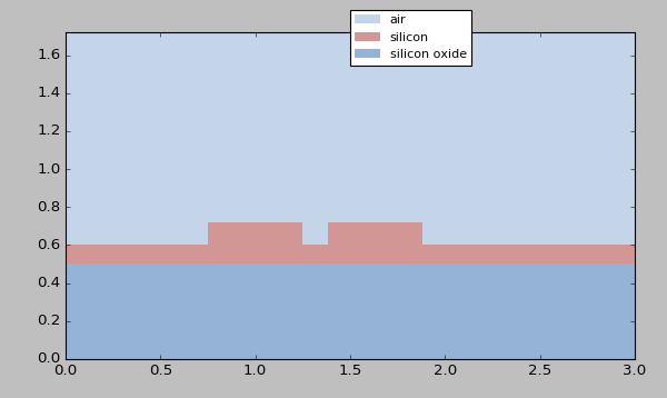
Cross-section virtual fabrication view