Advanced examples
There are situations in which you may need finer control in creating your layout. In this tutorial, we will go over some methods in which you can have this finer level of control.
Creating your own shapes - Exponential taper boundary
Let’s consider a situation in which you want to create your own component. This component uses unusual shapes that are not available among the shapes or shape elements in IPKISS. It is still possible to create such shapes, you need to do some lower-level programming to create them.
In our example, we want to create a component that looks like the following:
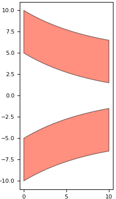
An exponential taper made with i3.Boundary
This is a taper created using two trenches that each follow an exponential path. The taper is defined as a negative such that it is the trenches, rather than the core, that are drawn on a layer.
There isn’t an element or a shape available out of the box in IPKISS that follows this shape.
However, we can create our own shape using i3.Shape and pass it to i3.Boundary to create our own custom element.
To achieve this, we will first take a look in the documentation to see if there is any shape that is similar the one we want.
We see that there is this shape, i3.ShapeExponential, that contains something similar.
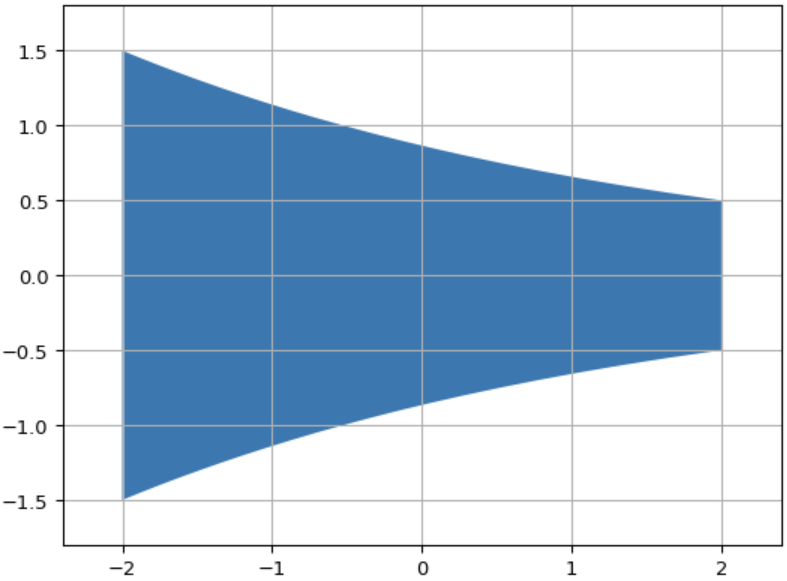
Visualization of i3.ShapeExponential
More specifically, we see that the top (and bottom) edge of this shape follows the same line that we want to create. The plan therefore is to copy the points from this existing shape, add the missing points we need, and create a new shape that fits our application.
Let’s take a look at how this is done in the code below:
class ExponentialTrench(i3.PCell):
    """A set of fixed width shapes either side of an exponential taper."""

    exponential_length = i3.PositiveNumberProperty(default=10, doc="Length of the taper.")
    begin_width = i3.PositiveNumberProperty(default=10, doc="Taper starting width.")
    end_width = i3.PositiveNumberProperty(default=3, doc="Taper end width.")
    trench_width = i3.PositiveNumberProperty(default=5, doc="Width of the trench.")
    layer = i3.LayerProperty(default=pdk.TECH.PPLAYER.SHALLOW_TRENCH, doc="Layer for the trench etch.")

    class Layout(i3.LayoutView):
        def _generate_elements(self, elems):
            shape_inner = i3.ShapeExponential(  # creating the inner taper
                begin_coord=(0, 0),
                begin_width=self.begin_width,
                end_coord=(self.exponential_length, 0),
                end_width=self.end_width,
            )

            # 2. We can take all the points in the inner taper shape, and filter out those below the x-axis, leaving us
            # with just the points along the top edge.  We then create a copy of these points with a translation that
            # matches our desired width.

            top_shape = i3.Shape(points=[coord for coord in shape_inner if coord.y > 0])
            top_shape_offset = top_shape.move_copy((0.0, self.trench_width))
            total_top_shape = top_shape + top_shape_offset.reversed()  # add the shapes and reverse one order of points
            total_bot_shape = total_top_shape.transform_copy(transformation=i3.VMirror())  # copy the top shape
            elems += i3.Boundary(layer=self.layer, shape=total_top_shape)  # create an element from the top shape
            elems += i3.Boundary(layer=self.layer, shape=total_bot_shape)
            return elems
We start by instantiating the shape i3.ShapeExponential with the values that we want.
To understand what we are doing, it is important to note that a shape in IPKISS contains a list of points which can be extracted or iterated over.
In this example, we take only the points in the shape that are above the y-axis.
This means that we obtain the points for an exponential line.
Then, we pass these points to the points property of a new instance of i3.Shape to create a shape with only these points.
This is done all in one line with the following code.
top_shape = i3.Shape(points=[coord for coord in shape_inner if coord.y > 0])
We call this shape top_shape as we use it for the top boundary of our exponential taper (the bottom boundary of our top trench).
We create a copy of this shape and offset it by the trench width to create the top boundary of the top trench.
top_shape_offset = top_shape.move_copy((0.0, self.trench_width))
In IPKISS we can add together different shapes, this creates a new shape with the list of points for each added together. By adding together the shape for the bottom boundary of the top trench to the shape for the top boundary in reverse order, we can create a total shape for the entire top trench.
total_top_shape = top_shape + top_shape_offset.reversed() # add the shapes and reverse one order of points
We can obtain the bottom shape by taking a copy of the top shape that is mirrored vertically (along the y-axis).
total_bot_shape = total_top_shape.transform_copy(transformation=i3.VMirror()) # copy the top shape
Then, we pass these shapes to i3.Boundary to create an element on a layer with these desired shapes.
elems += i3.Boundary(layer=self.layer, shape=total_top_shape)  # create an element from the top shape
elems += i3.Boundary(layer=self.layer, shape=total_bot_shape)
Creating a hierarchical layout - Racetrack resonator
It is possible to create a component out of other components.
The most convenient way to do so is by using i3.Circuit, but there are cases in which you may want a finer level of control.
In such cases, you can add references to the layout of certain components directly to other components.
To do this, you need to use the method _generate_instances of i3.LayoutView.
Much like for _generate_elements and _generate_ports, you need to overwrite the method in your LayoutView and have it return a list of reference elements that refer to the layout of another cell.
Let’s take a look at the following example in the code below:
class RacetrackResonator(i3.PCell):
    """Racetrack resonator based on the coupling gap and rind radius. By default, the total length is set to return a
    resonator with no vertical waveguides, but passing in a longer length will result in a rac"""

    _name_prefix = "RacetrackResonator"
    trace_template = i3.TraceTemplateProperty(doc="Trace template of the access waveguide and ring.")
    gap = i3.PositiveNumberProperty(default=1.0, doc="Gap between the edges of the access waveguide and racetrack.")
    length = i3.PositiveNumberProperty(doc="Total length of the racetrack resonator.")
    coupling_length = i3.NonNegativeNumberProperty(default=0.0, doc="Length of the straight coupling region.")
    radius = i3.PositiveNumberProperty(default=10.0, doc="Radius to the racetrack bends.")
    vertical_length = i3.NumberProperty(doc="Length of the vertical waveguides.")

    def _default_trace_template(self):
        return pdk.SiWireWaveguideTemplate()

    def _default_length(self):
        return np.pi * 2 * self.radius + 2 * self.coupling_length

    def _default_vertical_length(self):
        return (self.length - 2 * np.pi * self.radius - 2 * self.coupling_length) / 2

    # 1. It is possible to pass in parameters that are not physical, for example a very large bend radius, but a small
    # total length. We will use the "validate_properties()" method to enforce some rules on the parameters. Specifically
    # if a negative vertical length is needed to satisfy the equations then we know the total length is too small.

    def validate_properties(self):
        if self.vertical_length < 0.0:
            raise i3.PropertyValidationError(
                self,
                f"The current length is too small. It should be greater than "
                f"{round(2 * np.pi * self.radius + 2 * self.coupling_length, 4)} for the"
                f"the chosen radius and coupling",
                {"current_len": round(self.length, 4)},
            )
        return True

    class Layout(i3.LayoutView):
        # 2. Instead of the usual _generate_elements(), we are using _generate_instances() in our Layout view. It allows
        # us to add individual instances to the PCell, similar to building up an i3.Circuit. We will use it to add the
        # straight waveguides and bends separately.

        def _generate_instances(self, insts):
            core_width = self.trace_template.core_width

            bus_wg_shape = [  # create the shape of the bus waveguide
                (-self.radius - self.coupling_length / 2, 0.0),
                (self.radius + self.coupling_length / 2, 0.0),
            ]

            coupler_shape = [  # create the shape of the coupling waveguide
                (-self.coupling_length / 2, 0.0),
                (self.coupling_length / 2, 0.0),
            ]

            # 3. The i3.place_and_route() method allows us to build up the component similar to i3.Circuit, by creating
            # instances, then placing and connecting them. Here we place the straight waveguides in the correct places
            # then connect them with a circular bend to from our racetrack resonator.

            insts += i3.place_and_route(
                insts={
                    "bus_wg": i3.Waveguide(trace_template=self.trace_template).Layout(shape=bus_wg_shape),
                    "coupler_wg": i3.Waveguide(trace_template=self.trace_template).Layout(shape=coupler_shape),
                    "top_wg": i3.Waveguide(trace_template=self.trace_template).Layout(shape=coupler_shape),
                },
                specs=[
                    i3.Place("bus_wg", (0, 0)),
                    i3.Place("coupler_wg", (0, self.gap + core_width)),
                    i3.Place("top_wg", (0, self.gap + core_width + self.radius * 2 + self.vertical_length)),
                    i3.ConnectBend("coupler_wg:out", "top_wg:out", bend_radius=self.radius),
                    i3.ConnectBend("top_wg:in", "coupler_wg:in", bend_radius=self.radius),
                ],
            )
            return insts

        def _generate_ports(self, ports):  # we add ports in the usual way, at ends of our bus waveguide
            ports += i3.OpticalPort(
                name="in",
                position=(-self.radius - self.coupling_length / 2, 0),
                angle=180.0,
                trace_template=self.trace_template,
            )
            ports += i3.OpticalPort(
                name="out",
                position=(self.radius + self.coupling_length / 2, 0),
                angle=0.0,
                trace_template=self.trace_template,
            )
            return ports

    class Netlist(i3.NetlistFromLayout):
        pass
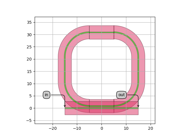
Default racetrack resonator layout
This PCell is used to create a racetrack resonator. This resonator consists of one bus waveguide and one waveguide that follows a loop used to implement a circle.
We need to first implement waveguides for the bus section, the couping section in the racetrack as well as in a top section.
To do so, we use the class i3.Waveguide.
This is a PCell for a waveguide included in IPKISS that takes as input the trace template, for defining a cross section, and a shape, for defining the trace along which it will be drawn.
i3.Waveguide and its layout combines this data together to create a waveguide layout.
See the image below for an illustration:
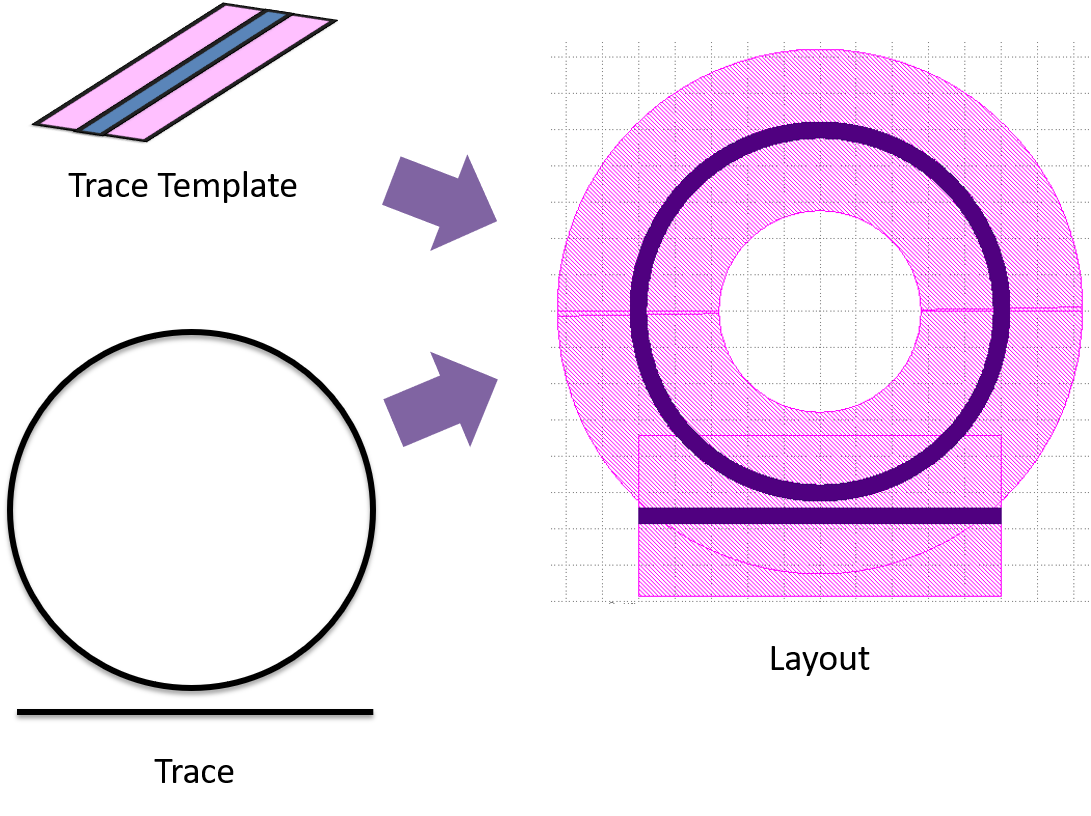
Creation of a waveguide from a trace and trace template
We define the shapes of our waveguides directly as a list of points:
            bus_wg_shape = [  # create the shape of the bus waveguide
                (-self.radius - self.coupling_length / 2, 0.0),
                (self.radius + self.coupling_length / 2, 0.0),
            ]

            coupler_shape = [  # create the shape of the coupling waveguide
                (-self.coupling_length / 2, 0.0),
                (self.coupling_length / 2, 0.0),
            ]
Then, we will be using the following code pattern to create our waveguides from the trace template that we define for our PCell and using these shapes:
i3.Waveguide(trace_template=self.trace_template).Layout(shape=bus_wg_shape) # copy the top shape
We use the placement and routing engine i3.place_and_route, to place our waveguides and connect them together:
            insts += i3.place_and_route(
                insts={
                    "bus_wg": i3.Waveguide(trace_template=self.trace_template).Layout(shape=bus_wg_shape),
                    "coupler_wg": i3.Waveguide(trace_template=self.trace_template).Layout(shape=coupler_shape),
                    "top_wg": i3.Waveguide(trace_template=self.trace_template).Layout(shape=coupler_shape),
                },
                specs=[
                    i3.Place("bus_wg", (0, 0)),
                    i3.Place("coupler_wg", (0, self.gap + core_width)),
                    i3.Place("top_wg", (0, self.gap + core_width + self.radius * 2 + self.vertical_length)),
                    i3.ConnectBend("coupler_wg:out", "top_wg:out", bend_radius=self.radius),
                    i3.ConnectBend("top_wg:in", "coupler_wg:in", bend_radius=self.radius),
                ],
            )
The i3.place_and_route function is in fact what i3.Circuit uses under the hood.
The latter however, although it requires more code, offers more flexibility, so is useful to know about.
What is returned from i3.place_and_route is a dictionary of i3.SRef instances.
These are references that point to the layout view of another cell.
You can add i3.SRef instances directly to the list returned by _generate_instances.
See Creating a Basic Layout for a tutorial that explains how to do that.