Directional Couplers
Directional couplers enable the transfer of light from one waveguide to another through evanescent coupling. In general, photonic directional couplers are implemented as two parallel waveguides.
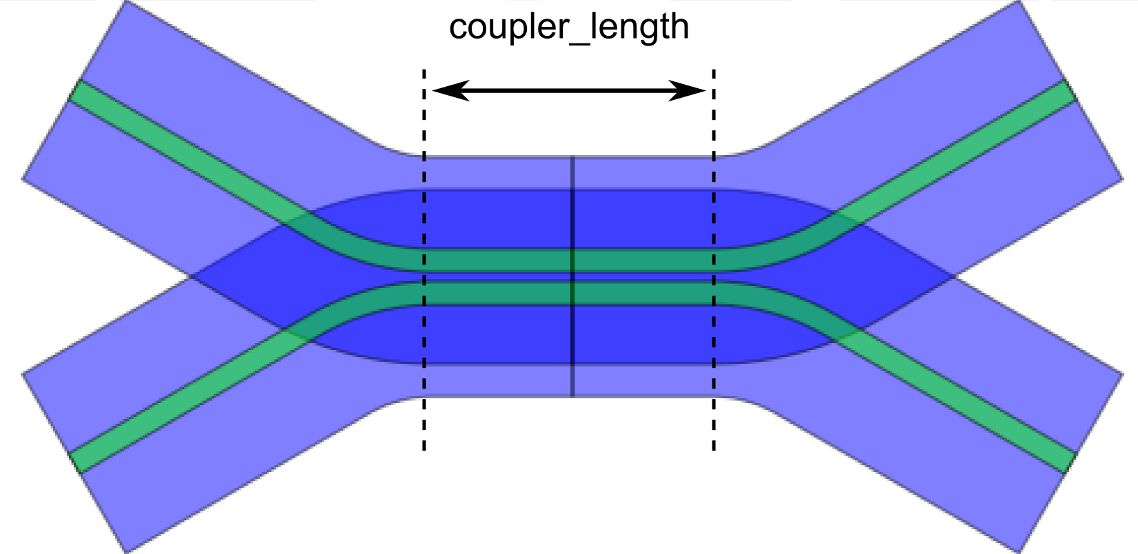
Example layout of a BendDirectionalCoupler.
The coupler_length PCell property is the length of the straight part of the coupler. There are different flavors of directional couplers:
A directional coupler consisting of 2 parallel (horizontal) straight waveguides. |
|
A directional coupler consisting of 2 parallel (horizontal) waveguides with bends at the start and end. |
|
A directional coupler consisting of 2 parallel (horizontal) waveguides with S-shaped bends at the start and end. |
CircuitModel details
In IPKISS, directional couplers are modeled using four waveguides and a logical coupler. The physical layout is built out of two waveguides, but the waveguides are split in a east and west part. This is done to match the layout and schematic, which is advantageous for circuit modeling and for verification purposes. The schematic is shown below:
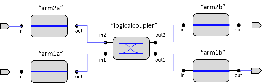
Schematic of a generic directional coupler.
Notice the logicalcoupler in the center. It is used for simulation purposes (and has no corresponding layout). The wave splitting occurs in this section. Two circuit models exist: CircuitModel and SimpleCircuitModel. Both use the physical length of the waveguides for the total phase propagation in the two arms. The model of the logicalcoupler differs:
CircuitModel: This model uses wavelength-independent fixed values for cross and bar coupling of the logicalcoupler.SimpleCircuitModel: This model uses a wavelength-dependent model for the logicalcoupler, based oncoupler_lengthand the difference in effective indices between the two supermodes inside the coupling section.