FiberCouplerCurvedGrating
- class picazzo3.fibcoup.curved.cell.FiberCouplerCurvedGrating
Class for the definition of periodic curved fiber grating couplers with a focal point that fit in a box.
- Parameters:
- inclination: float
out-of-plane angle of the grating coupler
- grating: PCell
grating of this fiber coupler
- wide_trace_template: PCell and _WaveguideTemplate
end waveguide for the socket waveguide (broad side)
- start_trace_template: PCell and _WaveguideTemplate
start waveguide for the socket waveguide (narrow side)
- socket: PCell and WgSocket
socket of the fiber coupler
- name: String that contains only ISO/IEC 8859-1 (extended ASCII py3) or pure ASCII (py2) characters
The unique name of the pcell
Views
- class Layout
This class generates a fiber grating coupler composed of a curved fiber grating with a LinearTransitionSocket. The origin of the coordinate system of the component is placed where the center of the fiber facet is assumed to have maximal coupling efficiency. This also the location of the vertical port
vertical_in.The grating lines generated by this class have the following properties.
1. All the grating lines have a shared focus point that is the east focus point of all the ellipses. The focus point has to be on the x-axis. The location of the focus is set by
focal_distance_xand will be located east of the origin.2. The first grating line will be drawn a distance
min_xfrom the focus point. So ifmin_x = 10, this means that the distance between the focus point and the first grating line will exactly be 10. By default, min_x is set to:3. All the grating lines are periodic in the x-direction with
period_x. This means that the distance between the intersections of grating lines with the x-axis is equal toperiod_x.4. All the grating lines are periodic in the y direction with
period_y. This means that the distance between the intersections grating lines with the y-axis is equal toperiod_y.The radius of the first ellipse in the y-direction is set be
start_radius_y.The radius of the first ellipse in the x-direction is automatically calculated and therefore locked.
7. All the grating lines fit in a box with width set by
box_widththat is symmetrically set along the x-axis. For example ifbox_widthis set to 10.0 all the grating lines will go fromy=-5.0toy=5.0.8. The width of all the grating lines is set by
fill_factor. A fill factor of 1 makes that the line width is a wide as the period. A fill factor of 0 makes sets the line_width to 0.The socket is a LinearTransitionSocket transitioning from the
start_trace_templatetowide_trace_template.start_trace_templateis the template seen at the focal point whilewide_trace_templateis the one seen at the location of the vertical port ``vertical_in`. The length of the transitionsocket_lengthis therefore locked and automatically set to thefocal_distance_x.To extend the taper beyond the focal point you can use the property
socket_extensionwhich will automatically prolong the taper with the lengthsocket_extensionThe default value ofextensionis chosen such that entire grating fits in the socket.- Parameters:
- fill_factor: float and fraction
Fill factor used to calculate the trench widths. 0 means no trench a all and 1 means that the trench covers the entire period
- purpose:
- process: ProcessLayer
default process used for the grating
- grating_transformation: GenericNoDistortTransform
- spread_angle: float
Angle in degrees of the far field radiation field of the socket.By default this is set to be equal to the angle of the taper that is set by its length and the width of the core of input and output waveguides.
- period_x: float and number > 0
Period in the x direction.
- min_x: float and number > 0
Minimum distance from the first line to the focus. By default it is set to the focal distance.
- focal_distance_x: float
Distance between the vertical port of the grating and the focal point. By default this is TECH.IO.FIBCOUP.CURVED.GRATING.FOCAL_DISTANCE.
- start_radius_y: float and number > 0
Starting radius in the y direction. By default this is set to
start_period_x- period_y: float and number > 0
Period in the y direction. By default equal to
period_x- box_width: float and number > 0
Width of the box used that contains the grating.
- n_o_lines: int and number > 0
Number of lines in the grating. By default this number is chosen so that the curves fit in the box width.
- socket_straight_extension: Coord2 and number >= 0
tuple: straight extension at start and end of socket
- socket_extension: float and Real, number and number >= 0
extension of the wide side of the socket, asymmetric with respect to the specified center. By default this is calculated such that the entire grating fits in the socket with a margin of TECH.IO.FIBCOUP.CURVED.DEFAULT_SOCKET_MARGIN_FROM_GRATING
- socket_transformation: GenericNoDistortTransform
- view_name: String that contains only alphanumeric characters from the ASCII set or contains _$. ASCII set is extended on PY3.
The name of the view
- Other Parameters:
- ellipse_radii_y: locked
- ellipse_radii_x: locked
- centers: locked
- focal_point: Coord2, locked
Coordinate of the east focus point shared by all ellipses. The y coordinate of the focuspoint has to be zero
- start_radius_x: locked
- line_widths: locked
Line width of the grating coupler
- end_angles: locked
- start_angles: locked
- socket_length: locked
Examples
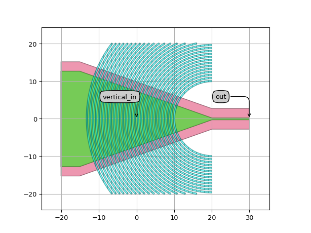
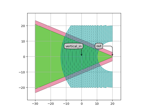
Basic use:
# Example demonstrating the basic use of the FiberGratingCoupler.
import si_fab.all as pdk  # noqa: F401
from ipkiss3 import all as i3

from picazzo3.fibcoup.curved import FiberCouplerCurvedGrating
from picazzo3.traces.wire_wg import WireWaveguideTemplate

# Creating the wire templates for the socket.
start_wg_tmpl = WireWaveguideTemplate()
start_wg_tmpl.Layout(core_width=0.5, cladding_width=2 * i3.TECH.WG.TRENCH_WIDTH + 0.5)
end_wg_tmpl = WireWaveguideTemplate()
end_wg_tmpl.Layout(core_width=17.0, cladding_width=2 * i3.TECH.WG.TRENCH_WIDTH + 17.0)

fc_cell = FiberCouplerCurvedGrating(start_trace_template=start_wg_tmpl, wide_trace_template=end_wg_tmpl)

fc_layout = fc_cell.Layout(
    period_x=0.8, focal_distance_x=20.0  # We with a period of 0.8
)  # We use a focal distance of 20.0

fc_layout.visualize(annotate=True)
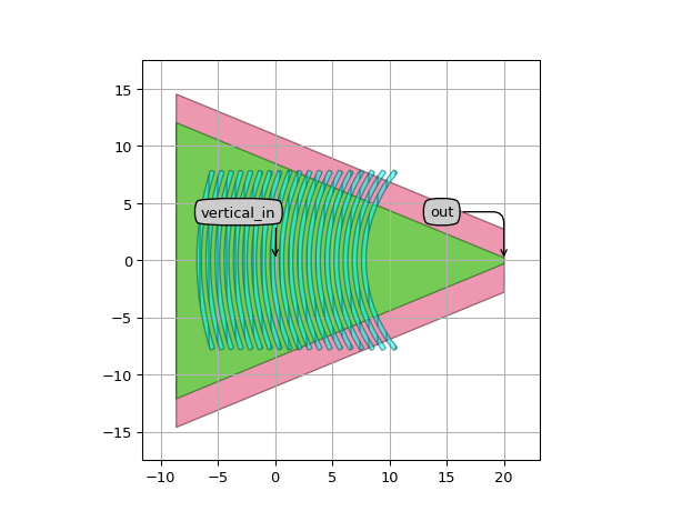
Changing the
n_o_linesand where to place the first line:# Example demonstrating how to change the length of the grating coupler using n_o_lines # and how to set the location of the first grating line using min_x import si_fab.all as pdk # noqa: F401 from ipkiss3 import all as i3 from picazzo3.fibcoup.curved import FiberCouplerCurvedGrating from picazzo3.traces.wire_wg import WireWaveguideTemplate # Creating the wire templates for the socket. start_wg_tmpl = WireWaveguideTemplate() start_wg_tmpl.Layout(core_width=0.5, cladding_width=2 * i3.TECH.WG.TRENCH_WIDTH + 0.5) end_wg_tmpl = WireWaveguideTemplate() end_wg_tmpl.Layout(core_width=17.0, cladding_width=2 * i3.TECH.WG.TRENCH_WIDTH + 17.0) fc_cell = FiberCouplerCurvedGrating(start_trace_template=start_wg_tmpl, wide_trace_template=end_wg_tmpl) fc_layout = fc_cell.Layout( period_x=0.8, # We with a period of 0.8 focal_distance_x=20.0, # We use a focal distance of 20.0 n_o_lines=30, # We set the number of lines to 30 min_x=10.0, # We set the first line at 10. ) fc_layout.visualize(annotate=True)

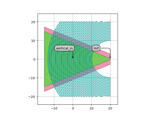
Changing the
box_width:# Example demonstrating how to change the box_width. import si_fab.all as pdk # noqa: F401 from ipkiss3 import all as i3 from picazzo3.fibcoup.curved import FiberCouplerCurvedGrating from picazzo3.traces.wire_wg import WireWaveguideTemplate # Creating the wire templates for the socket. start_wg_tmpl = WireWaveguideTemplate() start_wg_tmpl.Layout(core_width=0.5, cladding_width=2 * i3.TECH.WG.TRENCH_WIDTH + 0.5) end_wg_tmpl = WireWaveguideTemplate() end_wg_tmpl.Layout(core_width=17.0, cladding_width=2 * i3.TECH.WG.TRENCH_WIDTH + 17.0) fc_cell = FiberCouplerCurvedGrating(start_trace_template=start_wg_tmpl, wide_trace_template=end_wg_tmpl) fc_layout = fc_cell.Layout( period_x=0.8, # We with a period of 0.8 focal_distance_x=20.0, # We use a focal distance of 20.0. n_o_lines=30, # We set the number of lines to 30. min_x=10.0, # We set the first line at 10. box_width=40.0, # All the lines will be contained between -20 and 20 ) fc_layout.visualize(annotate=True)
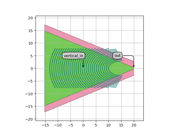
Changing the
fill_factorto set the line width:# Example demonstrating how to change the fill_factor. import si_fab.all as pdk # noqa: F401 from ipkiss3 import all as i3 from picazzo3.fibcoup.curved import FiberCouplerCurvedGrating from picazzo3.traces.wire_wg import WireWaveguideTemplate # Creating the wire templates for the socket. start_wg_tmpl = WireWaveguideTemplate() start_wg_tmpl.Layout(core_width=0.5, cladding_width=2 * i3.TECH.WG.TRENCH_WIDTH + 0.5) end_wg_tmpl = WireWaveguideTemplate() end_wg_tmpl.Layout(core_width=17.0, cladding_width=2 * i3.TECH.WG.TRENCH_WIDTH + 17.0) fc_cell = FiberCouplerCurvedGrating(start_trace_template=start_wg_tmpl, wide_trace_template=end_wg_tmpl) fc_layout = fc_cell.Layout( period_x=0.8, # We with a period of 0.8 focal_distance_x=20.0, # We use a focal distance of 20.0. n_o_lines=30, # We set the number of lines to 30. min_x=10.0, # We set the first line at 10. fill_factor=0.2, # Here we set the fill factor to 0.2 meaning that lines will be 0.2 * period_x thick ) fc_layout.visualize(annotate=True)

Changing the start radii in the y direction:
# Example that illustrates the degrees of freedom at your disposal concerning the
# periodicity and radii of the gratings in the y direction. You have more freedom in
# y direction since the focus is in the x-axis.

import si_fab.all as pdk  # noqa: F401
from ipkiss3 import all as i3

from picazzo3.fibcoup.curved import FiberCouplerCurvedGrating
from picazzo3.traces.wire_wg import WireWaveguideTemplate

# Creating the wire templates for the socket.
start_wg_tmpl = WireWaveguideTemplate()
start_wg_tmpl.Layout(core_width=0.5, cladding_width=2 * i3.TECH.WG.TRENCH_WIDTH + 0.5)
end_wg_tmpl = WireWaveguideTemplate()
end_wg_tmpl.Layout(core_width=17.0, cladding_width=2 * i3.TECH.WG.TRENCH_WIDTH + 17.0)

fc_cell = FiberCouplerCurvedGrating(start_trace_template=start_wg_tmpl, wide_trace_template=end_wg_tmpl)

fc_layout = fc_cell.Layout(
    focal_distance_x=20.0,  # We use a focal distance of 20.0.
    n_o_lines=30,  # We use 30 lines.
    period_x=0.8,  # We with a period of 0.8
    period_y=0.5,  # period has to be smaller than the period in the x direction
    start_radius_y=3.0,  # Start_radius_y has to be smaller than min_x
    fill_factor=0.2,  # Fill factor of 0.2
    min_x=10.0,  # First line at 10.0
)

fc_layout.visualize(annotate=True)
Changing the socket extensions:
# Example demonstrating how to change the socket_extension.
import si_fab.all as pdk  # noqa: F401
from ipkiss3 import all as i3

from picazzo3.fibcoup.curved import FiberCouplerCurvedGrating
from picazzo3.traces.wire_wg import WireWaveguideTemplate

# Creating the wire templates for the socket.
start_wg_tmpl = WireWaveguideTemplate()
start_wg_tmpl.Layout(core_width=0.5, cladding_width=2 * i3.TECH.WG.TRENCH_WIDTH + 0.5)
end_wg_tmpl = WireWaveguideTemplate()
end_wg_tmpl.Layout(core_width=17.0, cladding_width=2 * i3.TECH.WG.TRENCH_WIDTH + 17.0)

fc_cell = FiberCouplerCurvedGrating(start_trace_template=start_wg_tmpl, wide_trace_template=end_wg_tmpl)

fc_layout = fc_cell.Layout(
    period_x=0.8,  # We with a period of 0.8
    focal_distance_x=20.0,  # We use a focal distance of 20.0.
    n_o_lines=30,  # We set the number of lines to 30.
    min_x=10.0,  # We set the first line at 10.
    box_width=40.0,  # All the lines will be contained between -20 and 20
    socket_extension=30.0,  # A socket extension will of 30.0 will be added
)

fc_layout.visualize(annotate=True)
Changing the straight socket extensions:
# Example demonstrating how to change the socket_straight_extensions.
import si_fab.all as pdk  # noqa: F401
from ipkiss3 import all as i3

from picazzo3.fibcoup.curved import FiberCouplerCurvedGrating
from picazzo3.traces.wire_wg import WireWaveguideTemplate

# Creating the wire templates for the socket.
start_wg_tmpl = WireWaveguideTemplate()
start_wg_tmpl.Layout(core_width=0.5, cladding_width=2 * i3.TECH.WG.TRENCH_WIDTH + 0.5)
end_wg_tmpl = WireWaveguideTemplate()
end_wg_tmpl.Layout(core_width=17.0, cladding_width=2 * i3.TECH.WG.TRENCH_WIDTH + 17.0)

fc_cell = FiberCouplerCurvedGrating(start_trace_template=start_wg_tmpl, wide_trace_template=end_wg_tmpl)

fc_layout = fc_cell.Layout(
    period_x=0.8,  # We with a period of 0.8
    focal_distance_x=20.0,  # We use a focal distance of 20.0.
    n_o_lines=30,  # We set the number of lines to 30.
    min_x=10.0,  # We set the first line at 10.
    box_width=40.0,
    # A straight extension of 10.0 will be added at the
    # narrow side and 5.0 at the wide part of the socket.
    socket_straight_extension=(10.0, 5.0),
)

fc_layout.visualize(annotate=True)