Scatter matrix: a mathematical primer
This is a short mathematical introduction into scatter matrices.
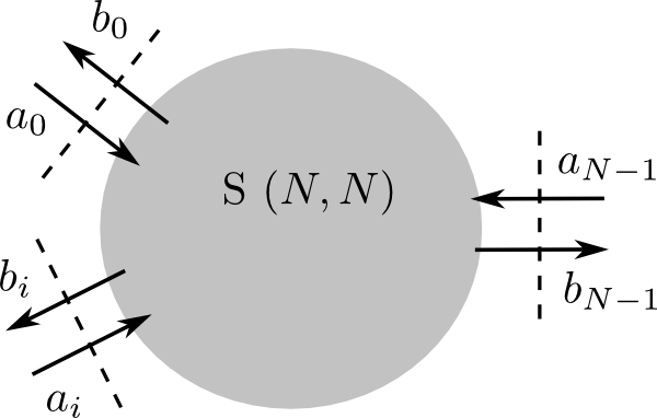
In a passive, linear circuit, we can treat an optical structure as a black box which exchanges energy with the outside world through several physical outlets. Figure An optical structure as a black box with several terms. shows how a structure has different physical outlets, which we will call optical terms (or terms, in short). These terms can be associated with an optical waveguide mode, or a free space electromagnetic beam.

An optical structure as a black box with several terms.
We define
Where we have defined the scatter matrix
Note
In this description, the different modes are expanded into different terms. So, suppose a component has four physical terms, and there are two modes per term, the S-matrix has the following dimension: (8 x 8).
Attention
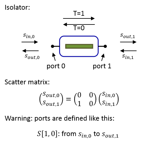
Due to the way the scatter matrix is defined, S[a, b] means: from port b to port a. For reciprocal devices (which is usually the case), S[a, b] = S[b, a], so it doesn’t matter in which direction you look at the transmission. But when working with Non-reciprocal devices, it is very important to be aware of this.
Properties of the scatter matrix
Depending on the actual material properties and geometry inside the structure, the component can have two interesting properties: passivity and reciprocity.
passivity: A component is told to be passive when it is unable to generate energy. This means that (we assume the
for all possible values of
For a lossless component, the equality holds. In this case, this is equivalent to the condition that
where
When the
reciprocal: If a circuit is made of symmetrical constitutive parameters, i.e. the permittivity
and hence the transmission between two ports does not depend on the propagation direction.
See also:
Non-reciprocal devices
Please note that, because of

Example of a non-reciprocal component: an optical isolator.
Please keep this in mind when you define non-reciprocal devices.
See also:
Piero Triverio, Stefano Grivet-Talocia, Michel S Nakhla, Flavio G Canavero, and Ramachandra Achar. Stability, causality, and passivity in electrical interconnect models. Advanced Packaging, IEEE Transactions on, 30(4):795–808, 2007.