ConnectManhattan
- class ipkiss3.all.ConnectManhattan
A connector that uses
i3.RouteManhattanto connect two ports and returns an instance of i3.RoundedWaveguide (optical ports) or i3.ElectricalWire (electrical ports).This connector is supposed to be used together with
i3.place_and_route.Note
Electrical ports need to have an angle (not None) for the routing algorithm to work.
- Parameters:
- cover_layers: List with type restriction, allowed types: <class ‘ipkiss.primitives.layer.Layer’>, optional
Layers that can be used to generate additional coverage of the trace (e.g. manhattan corners). The ‘cover_bends’ property has to be set to True for this to take effect.
- cover_bends: ( bool, bool_ or int ), optional
Adds rectangular blocks in the bends to avoid as much as possible non-manhattan angles. Needs to be configured together with the ‘cover_layers’ property.
- fixed_bend90: ( PCell ), optional, *None allowed*
An optional override for the 90 degree bends used in the routing. The bend should have exactly two optical ports and the angle of the bend should be equal to 90 degrees. The trace template of the bend should match trace_template. Bends are assumed to be bi-directional in the routing. If the route requires non 90 degree angles, they will generated using bend_radius, angle_step and rounding_algorithm. Likewise when there isn’t enough space to place the fixed bend, it will be replaced by an autogenerated one.
- min_spacing: float and Real, number and number >= 0, optional
minimal spacing between parallel sections of the route
- end_straight: float and Real, number and number >= 0, optional
The length of the straight end section of the route
- start_straight: float and Real, number and number >= 0, optional
The length of the straight start section of the route
- min_straight: float and Real, number and number >= 0, optional
The minimum length of any straight sections in the route
- angle_step: float and number > 0, optional
angle step for rounding
- rounding_algorithm: optional
Rounding algorithm (ShapeRound, ShapeRoundAdiabaticSpline, …). Takes a shape as input and returns a new (rounded) shape.
- bend_radius: float and number > 0, optional
bend radius for the auto-generated bends
- control_points: list, optional
Control the routing by passing either a list of points
i3.CPthrough which the route has to pass,or a list ofi3.H/i3.Vinstances.- trace_template: ( PCell and _TraceTemplate ), optional, *None allowed*
Trace template to use for the waveguide between the two ports, when the ports have a different template, transitions will be added. When this property is left unspecified/None the trace_template of the start_port will be used
See also
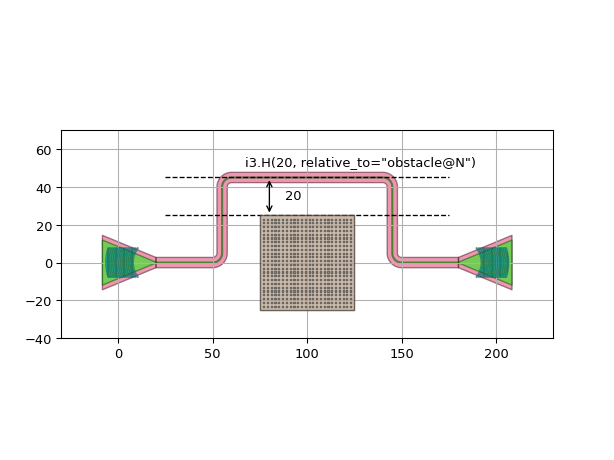
Examples
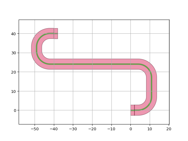
"""
This example illustrations how you can use the control_points property to guide
your waveguide around an obstacle.
"""
import si_fab.all as pdk  # noqa: F401
from picazzo3.fibcoup.curved import FiberCouplerCurvedGrating
from ipkiss3 import all as i3
import matplotlib.pyplot as plt

# Placing the components in a circuit
gr = FiberCouplerCurvedGrating()
control_points = [i3.CP((-40, 20), i3.NORTH), i3.CP((0, 30), i3.EAST), i3.CP((50, 20), i3.SOUTH)]
circuit = i3.Circuit(
    insts={"gr": gr, "grb1": gr, "grb2": gr},
    specs=[
        i3.Place("gr", position=(0, 0)),
        i3.Place("grb1", position=(-100, 0)),
        i3.Place("grb2", position=(+100, 0), angle=180),
        i3.ConnectManhattan(
            "grb1:out",
            "grb2:out",
            control_points=control_points,
        ),
    ],
)
circuit_layout = circuit.Layout()
circuit_layout.visualize(show=False)
plt.scatter([cp[0] for cp in control_points], [cp[1] for cp in control_points], c="C1", s=80, marker="x")
plt.arrow(-40, 20, 0, 2, width=1.0)
plt.arrow(0, 30, 2, 0, width=1.0)
plt.arrow(50, 20, 0, -2, width=1.0)
plt.show()
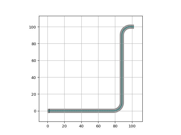
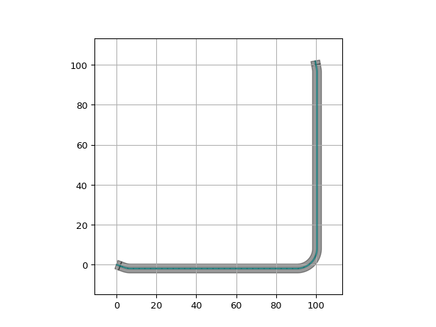
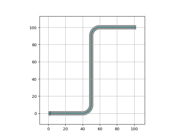
import si_fab.all as pdk  # noqa: F401
import ipkiss3.all as i3
from picazzo3.traces.rib_wg.trace import RibWaveguideTemplate

# Instantiate trace templates to use for the ports
tt1 = RibWaveguideTemplate()
tt1.Layout(core_width=0.5)

# Define some ports
port1 = i3.OpticalPort(position=(0.0, 0.0), angle=0.0, trace_template=tt1)
port2 = i3.OpticalPort(position=(100.0, 100.0), angle=180.0, trace_template=tt1)
# Ports with non-manhattan angles:
port3 = i3.OpticalPort(position=(0.0, 0.0), angle=-20.0, trace_template=tt1)
port4 = i3.OpticalPort(position=(50.0, 70.0), angle=100.0, trace_template=tt1)

# Create the connection
wg = i3.ConnectManhattan.connect(port1, port2, name="manhattan_connection", bend_radius=10.0)
lo = wg.get_default_view(i3.LayoutView)
lo.visualize()

wg = i3.ConnectManhattan.connect(port3, port4, name="manhattan_connection2", bend_radius=10.0)
lo = wg.get_default_view(i3.LayoutView)
lo.visualize()


import ipkiss3.all as i3

input_port = i3.OpticalPort(name="in", position=(0.0, 0.0), angle=0.0)
output_port = i3.OpticalPort(name="out", position=(-40.0, 40.0), angle=180.0)
bend_radius = 7.0

ra = i3.ShapeRound
wg = i3.ConnectManhattan.connect(
    start_port=input_port, end_port=output_port, bend_radius=bend_radius, rounding_algorithm=ra
)
wg.get_default_view(i3.LayoutView).visualize()

ra = i3.SplineRoundingAlgorithm(adiabatic_angles=(15, 15))
wg = i3.ConnectManhattan.connect(
    start_port=input_port, end_port=output_port, bend_radius=bend_radius, rounding_algorithm=ra
)
wg.get_default_view(i3.LayoutView).visualize()
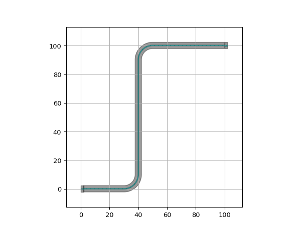
import si_fab.all as pdk  # noqa: F401
import ipkiss3.all as i3
from picazzo3.traces.rib_wg.trace import RibWaveguideTemplate

# Instantiate trace templates to use for the ports
tt1 = RibWaveguideTemplate()
tt1.Layout(core_width=0.5)

# Define some ports
port1 = i3.OpticalPort(position=(0.0, 0.0), angle=0.0, trace_template=tt1)
port2 = i3.OpticalPort(position=(100.0, 100.0), angle=180.0, trace_template=tt1)
# Ports with non-manhattan angles:
port3 = i3.OpticalPort(position=(0.0, 0.0), angle=-20.0, trace_template=tt1)
port4 = i3.OpticalPort(position=(50.0, 70.0), angle=100.0, trace_template=tt1)

# Create the connection with control_points.
# The route will go through point (50, 50):
wg = i3.ConnectManhattan.connect(
    port1, port2, name="manhattan_connection", control_points=[(50, 50)], bend_radius=10.0
)
lo = wg.get_default_view(i3.LayoutView)
lo.visualize()

# Another option for control_points is to describe the horizontal and vertical parts of the route.
# You can do this in the following way:
# [V(40)] describes that the route should be vertical at x = 40.
wg = i3.ConnectManhattan.connect(
    port1, port2, name="manhattan_connection2", control_points=[i3.V(40)], bend_radius=10.0
)
lo = wg.get_default_view(i3.LayoutView)
lo.visualize()

# [V(100), H(100)] determines that the route should be vertical at x = 100 and then horizontal at y = 100.
wg = i3.ConnectManhattan.connect(
    port3, port4, name="manhattan_connection3", control_points=[i3.V(100), i3.H(100)], bend_radius=10.0
)
lo = wg.get_default_view(i3.LayoutView)
lo.visualize()

# Note 1: These two types of control points don't mix: [V(20), (50, 50), H(10)] is not allowed.
# Note 2: When using more than one horizontal and/or vertical control points an H must always follow a V,
# and vice versa. You can't pass two of the same type right after each other. For instance:
# [V(20), V(30), H(10)] is not allowed, [V(20), H(20), V(30), H(10)] is allowed.
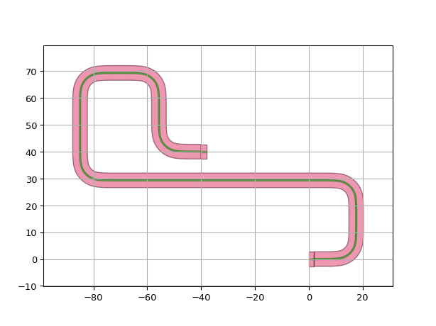

import si_fab.all as pdk  # noqa: F401
import ipkiss3.all as i3
from picazzo3.traces.rib_wg.trace import RibWaveguideTemplate
from ipkiss3.all import START, END

# Instantiate trace templates to use for the ports
tt1 = RibWaveguideTemplate()
tt1.Layout(core_width=0.5)

# Define some ports
port1 = i3.OpticalPort(position=(0.0, 0.0), angle=0.0, trace_template=tt1)
port2 = i3.OpticalPort(position=(100.0, 100.0), angle=180.0, trace_template=tt1)

control_points = [
    START + (30, 10),  # control point at (30, 10) relative to the start port
    (50, 50),  # control point at (50, 50) relative to (0, 0)
    END - (30, 10),
]  # control point at (-30, -10) relative to the end port

wg = i3.ConnectManhattan.connect(
    port1, port2, name="manhattan_connection", control_points=control_points, bend_radius=5.0
)
lo = wg.get_default_view(i3.LayoutView)
lo.visualize()

# Similarly it is possible to define relative i3.H and i3.V control points
wg = i3.ConnectManhattan.connect(
    port1, port2, name="manhattan_connection2", control_points=[i3.H(END - 40)], bend_radius=5.0
)
lo = wg.get_default_view(i3.LayoutView)
lo.visualize()
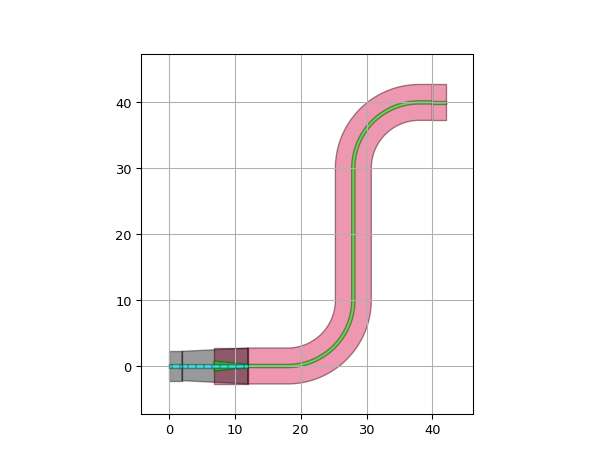
When required ConnectManhattan will introduce transitions to create a valid connection.:
import si_fab.all as pdk  # noqa: F401
import ipkiss3.all as i3
from picazzo3.traces.rib_wg.trace import RibWaveguideTemplate
from picazzo3.traces.wire_wg.trace import WireWaveguideTemplate

# Instantiate trace templates to use for the ports
tt_start = RibWaveguideTemplate()
tt_start.Layout(core_width=0.5)

tt_end = WireWaveguideTemplate()
tt_end.Layout(core_width=0.5)

start_port = i3.OpticalPort(position=(0.0, 0.0), angle=0.0, trace_template=tt_start)
end_port = i3.OpticalPort(position=(40.0, 40.0), angle=180.0, trace_template=tt_end)

# The connecting waveguide will use the trace_template specified
# on the start_port and introduce a transition at the end
# to connect properly with the end_port.
wg = i3.ConnectManhattan.connect(start_port, end_port, bend_radius=10.0)
lo = wg.get_default_view(i3.LayoutView)
lo.visualize(annotate=True)

By default ConnectManhattan will use the trace_template from the start_port for the connecting waveguide, but this can be changed using the trace_template property:
def __example7_transitioning(self):
    import si_fab.all as pdk  # noqa: F401
    import ipkiss3.all as i3
    from picazzo3.traces.rib_wg.trace import RibWaveguideTemplate
    from picazzo3.traces.wire_wg.trace import WireWaveguideTemplate

    # Instantiate trace templates to use for the ports
    tt_start = RibWaveguideTemplate()
    tt_start.Layout(core_width=0.5)

    tt_end = WireWaveguideTemplate()
    tt_end.Layout(core_width=0.5)

    start_port = i3.OpticalPort(position=(0.0, 0.0), angle=0.0, trace_template=tt_start)
    end_port = i3.OpticalPort(position=(40.0, 40.0), angle=180.0, trace_template=tt_end)

    # use the trace_template of the end_port
    # this will add the transition at the start port rather
    # than at the end port.
    wg = i3.ConnectManhattan.connect(start_port, end_port, bend_radius=10.0, trace_template=tt_end)
    lo = wg.get_default_view(i3.LayoutView)
    lo.visualize(annotate=True)
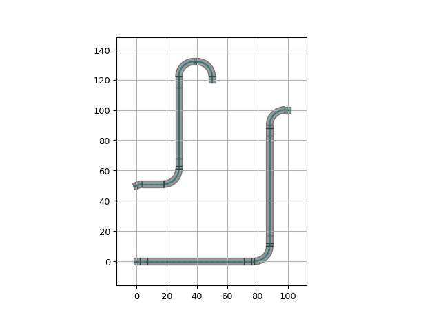
If you want to have more control over the bends, you can provide the fixed_bend90 parameter.:
"""Example showcasing fixed bend usage"""
import si_fab.all as pdk  # noqa: F401
import ipkiss3.all as i3
from picazzo3.traces.rib_wg.trace import RibWaveguideTemplate

# Trace template for the ports
tt1 = RibWaveguideTemplate()
tt1.Layout(core_width=0.5)

# Bend to use for the 90 degree sections
bend = i3.RoundedWaveguide(trace_template=tt1)
bend.Layout(shape=[(-10.0, 0.0), (0.0, 0.0), (0, 10.0)], bend_radius=10.0)

wg = i3.Waveguide(trace_template=tt1).Layout()

circuit = i3.Circuit(
    insts={
        "wg1": wg,
        "wg2": wg,
        "wg3": wg,
        "wg4": wg,
    },
    specs=[
        i3.Place("wg1:in", position=(0, 0), angle=0.0),
        i3.Place("wg2:in", position=(100, 100), angle=180.0),
        i3.Place("wg3:in", position=(0, 50), angle=20),
        i3.Place("wg4:in", position=(50, 50 + 70), angle=90.0),
        i3.ConnectManhattan(
            [
                ("wg1:in", "wg2:in"),
                ("wg3:in", "wg4:in"),
            ],
            bend_radius=5.0,
            trace_template=tt1,
            fixed_bend90=bend,
        ),
    ],
)

lo = circuit.get_default_view(i3.LayoutView)
lo.visualize()
Covers can be added to the bends on a specified layer.:
import si_fab.all as pdk  # noqa: F401
import ipkiss3.all as i3

port1 = i3.OpticalPort(name="in_top", position=(0.0, 0.0), angle=0.0)
port2 = i3.OpticalPort(name="out_top", position=(15.0, 15.0), angle=-90.0)

wg = i3.ConnectManhattan.connect(
    start_port=port1,
    end_port=port2,
    bend_radius=7.0,
    cover_bends=True,
    cover_layers=[i3.TECH.PPLAYER.SI_CLADDING],
)

lo = wg.get_default_view(i3.LayoutView)
lo.visualize()