AWG Components
Overview
In the AWG Designer, 5 different concepts are needed to design and implement an AWG:
Slab Template
Free Propagation Region
Aperture
Star Coupler
Waveguide Array
These components are finally combined into an AWG. If you control each of these, then you control the AWG device. In the next sections, we go into more detail about each component type.
The AWG consists of 3 subcomponents:
The input Star Coupler
The Waveguide Array
The output Star Coupler
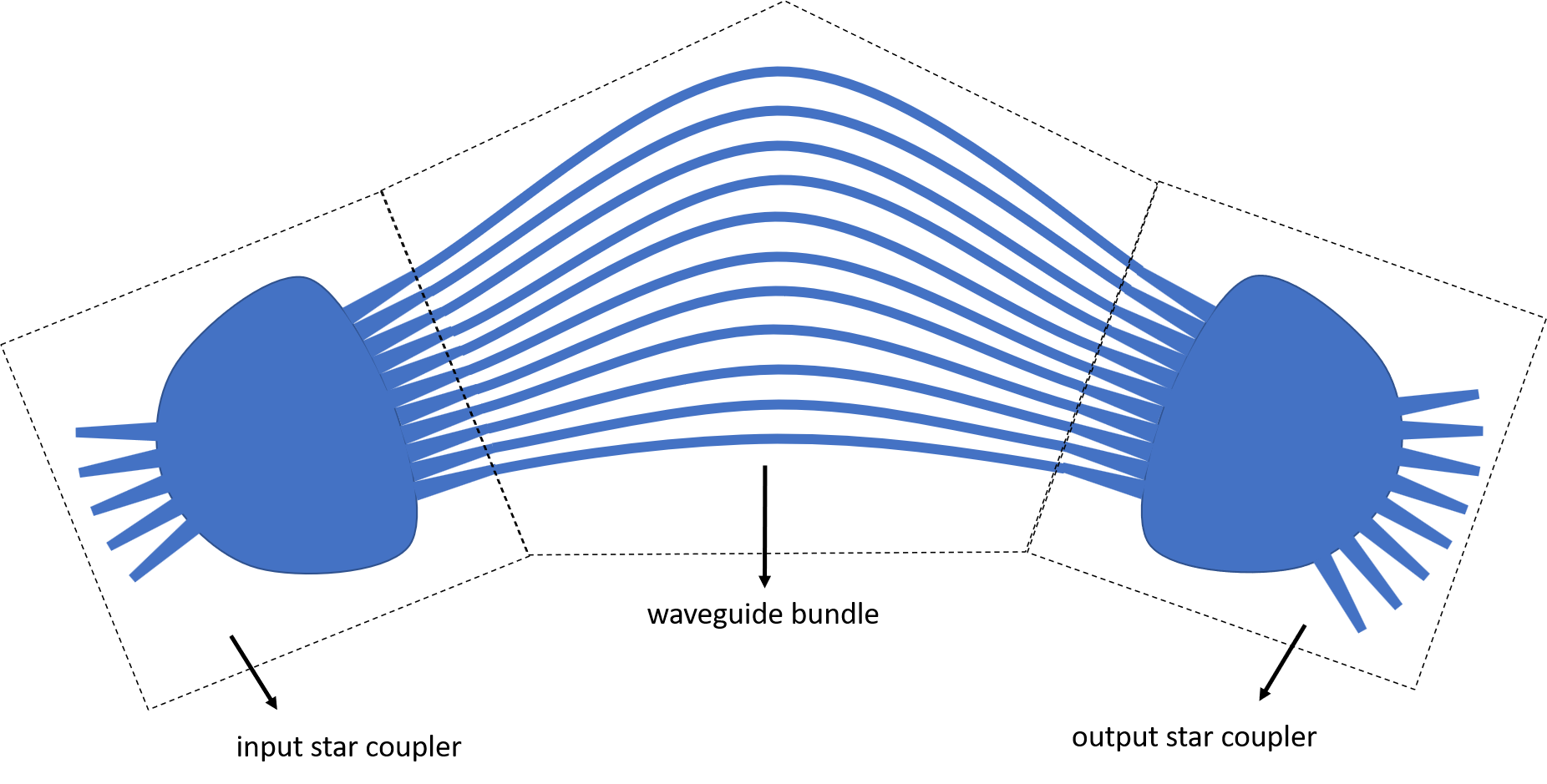
Components of the AWG
Each star coupler consists of 3 subcomponents as well:
The input Apertures
The Free Propagation Region, characterized by a Slab Template which contains the cross-section information
The output Apertures
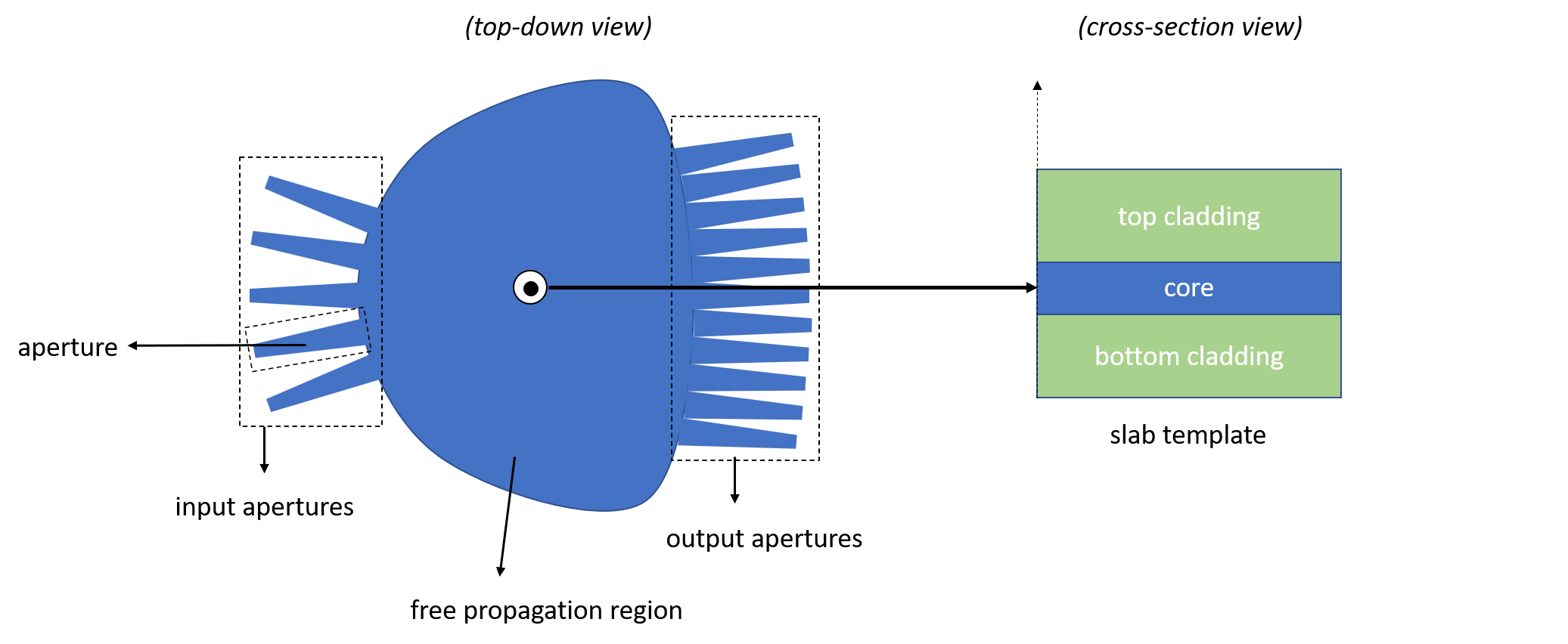
Components of the Star Coupler
Slab Template
The template awg_designer.all.SlabTemplate describes the cross-section and modes of the free propagation region. It is implemented in the awg_designer module.
We can visualize its properties to ensure correctness. The cross-section can be obtained from its layout view:
import si_fab.all as pdk
import ipkiss3.all as i3
from awg_designer.all import SlabTemplate
import numpy as np

# Instantiate Slab
slab = SlabTemplate()

# Visualize cross-section
slab_layout = slab.Layout(slab_layers=[i3.TECH.PPLAYER.SI])
slab_xs = slab_layout.cross_section()
slab_xs.visualize()
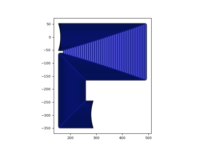
The slab waveguide’s modes can be obtained automatically by running a CAMFR simulation on the cross-section. Two inputs are essential:
The wavelength range withing which we calculate the modes. Here, we select the band between 1.25 um and 1.35 um.
The material models, verified in the previous step.
The resulting mode effective indices can be plotted and checked easily:
# Calculate and visualize modes
wavelengths = np.linspace(1.25, 1.35, 101)
slab_modes = slab.SlabModesFromCamfr(wavelengths=wavelengths)
slab_modes.visualize(wavelengths=wavelengths)
Apertures
Apertures feed the light in and out of the star couplers.
You can find a full tutorial on how to build your own apertures here
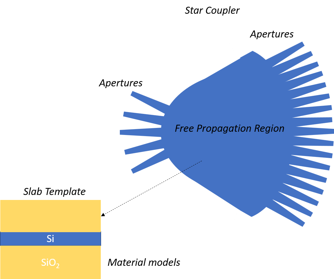
Star Coupler
A star coupler is the combination of the in and out apertures with the free propagation region.
An AWG consists of two of these star couplers that are connected through the waveguide array.
To create a star coupler you can use the awg_designer.all.StarCoupler class.
Free Propagation Region
The light is diffracted through the input apertures and propagates through the slab area
The FPR region or contour can be calculated using awg_designer.all.get_star_coupler_extended_contour().
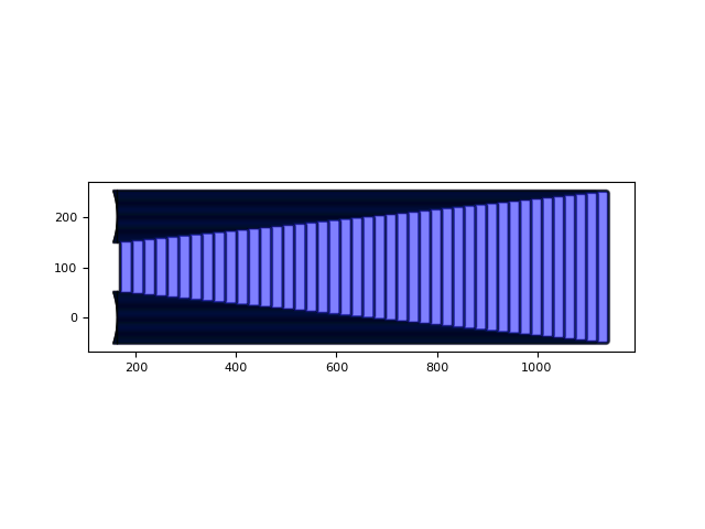
Waveguide Array
The waveguide array consists of waveguides with a length difference, implementing the phased array behavior of the AWG. They connect the out and in apertures of the input and output star-couplers respectively. By changing the length of these waveguides a different phase shift is applied. Two types of waveguide array can be made.
The rectangular waveguide array (awg_designer.all.RectangularWaveguideArray )
and the s-shaped waveguide array (awg_designer.all.SWaveguideArray)