Reusing cells in circuits
In this section we explain how to build a new cell in L-Edit, that can be reused in user designs.
We will go through the following steps:
Create a new design MZI in the filters_ledit library
Instantiate a splitter and a combiner
Draw waveguides between the splitter and combiner
Propagate the unconnected ports (the input of the splitter, the output of the combiner)
Create a new design test_design_mzi
Instantiate several MZI components and grating couplers, draw waveguide routes
Finish by generating the waveguides
The crucial step here is step 4: this ensures that the unconnected ports are recognized in step 6. If you are routing waveguides, there always has to be a port defined.
Create the MZI design
Create a new design MZI
Instantiate a splitter and a combiner
We start by creating an MZI cell in the filters_ledit library (see figures below).
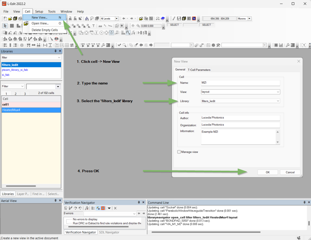
In the filters_ledit library, create a new cell called MZI.
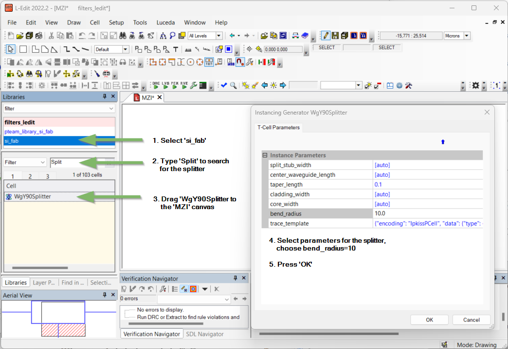
Instantiate a splitter (one for splitting, one for combining).
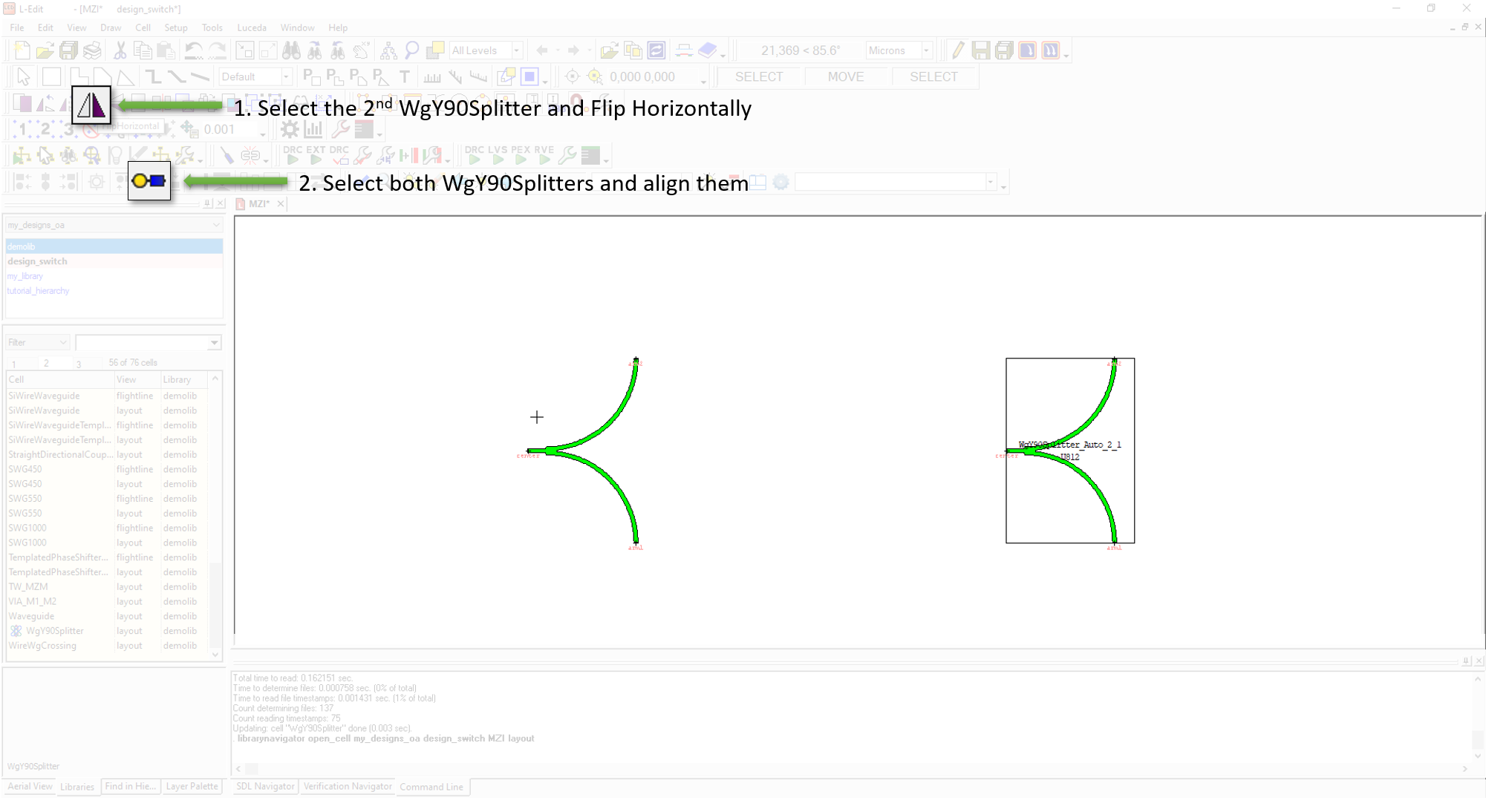
Place, align and mirror the components.
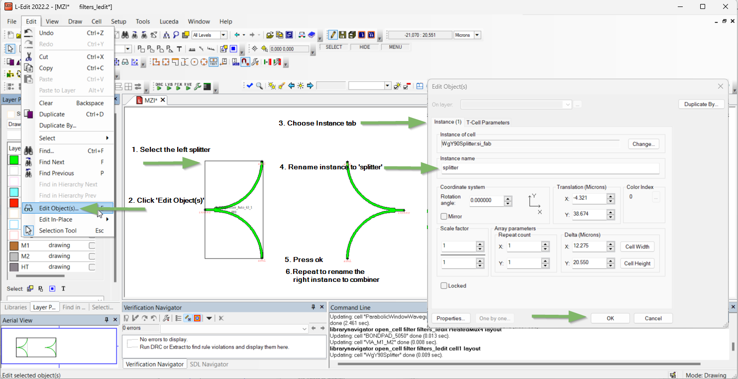
Rename the first splitter to splitter, rename the second to combiner.
We generate the waveguide control shapes, and generate the waveguides, as shown in Figure Generate the waveguides and Figure Propagate the ports.
Draw waveguides between the splitter and the combiner
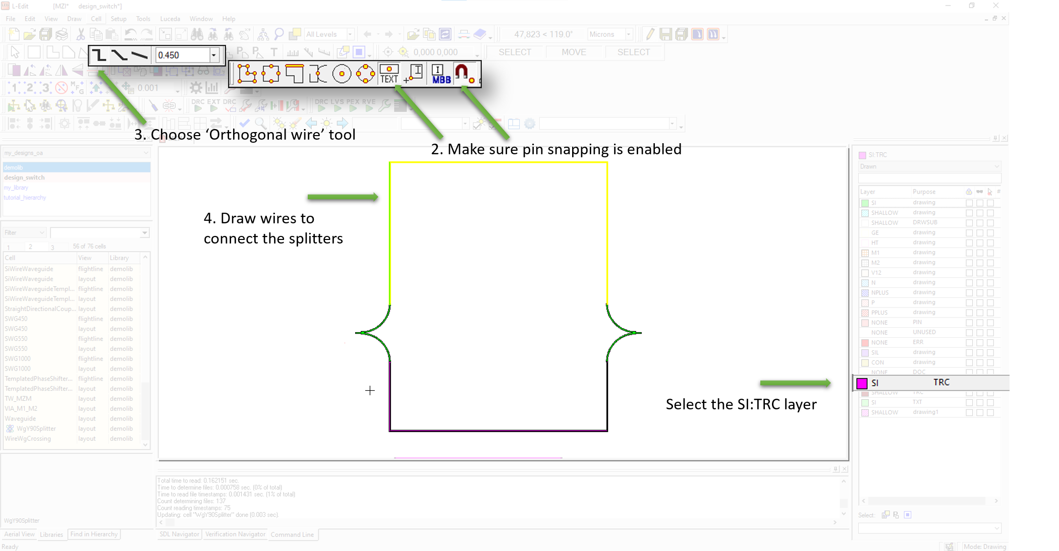
Draw the waveguide control shapes on the SI:TRC layer.
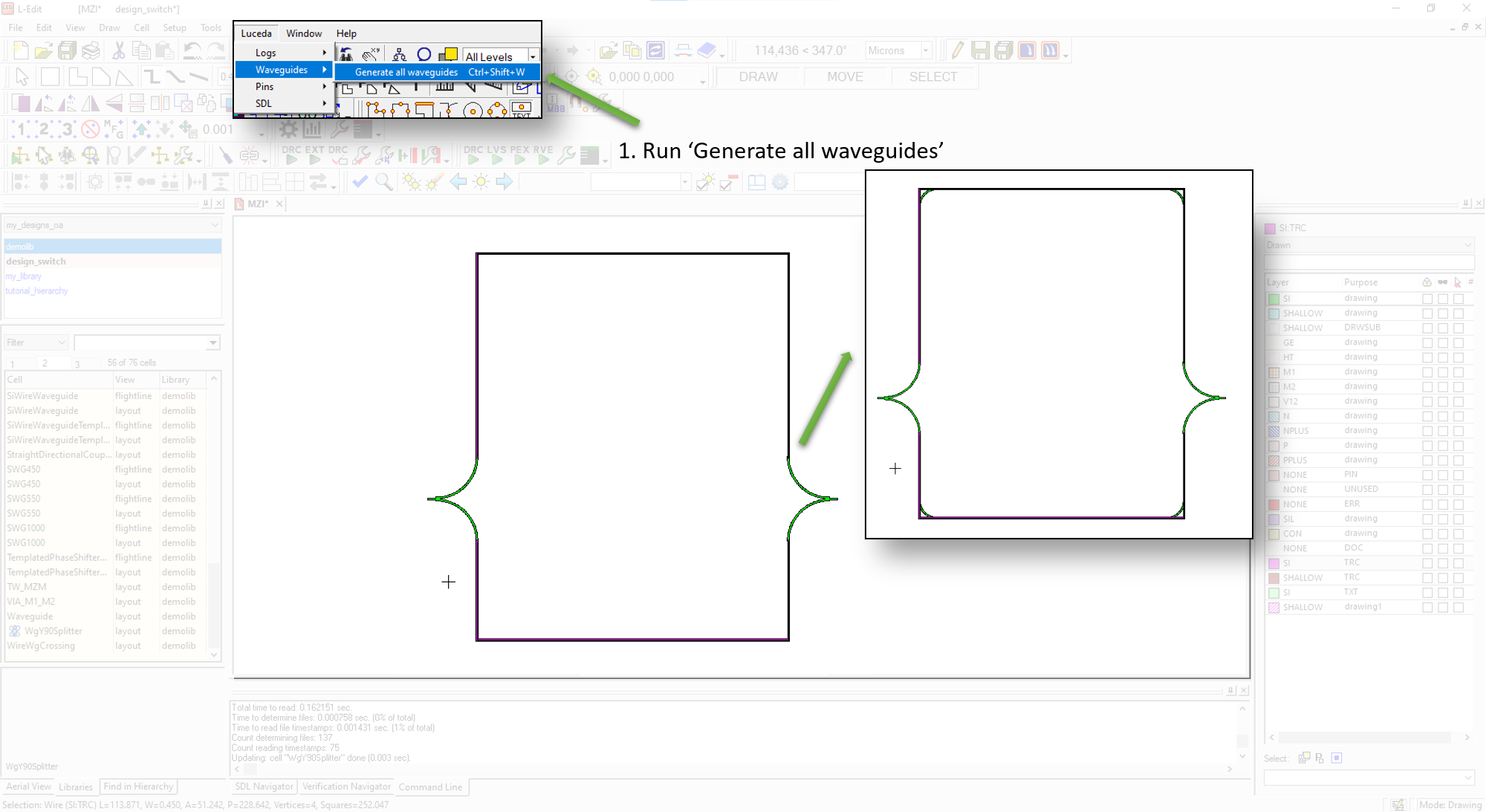
Generate the waveguides (from menu bar, )
To finalize our component, we need to ensure the unconnected ports are duplicated in the top-level design. That way, we will be able to use these ports in other designs as well. To do so, we use the Propagate pins function from the Luceda menu.
Propagate the unconnected ports
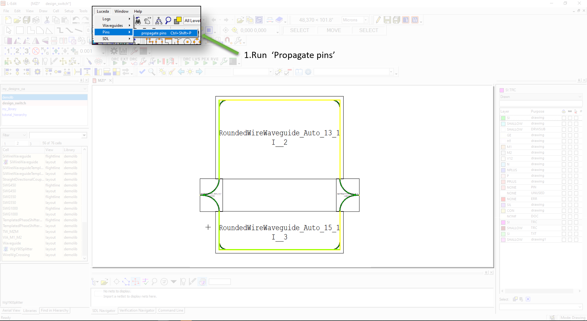
Propagate the ports (from menu bar, ).
Create the test design
Create a new design test_design_mzi
Instantiate several MZI components and grating couplers, draw waveguide routes
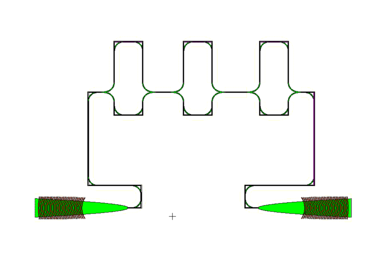
We now create a test design, in which we cascade three MZI components. We then connect the MZIs themselves, and connect the two of them to fiber couplers (Figure Cascaded MZI components).
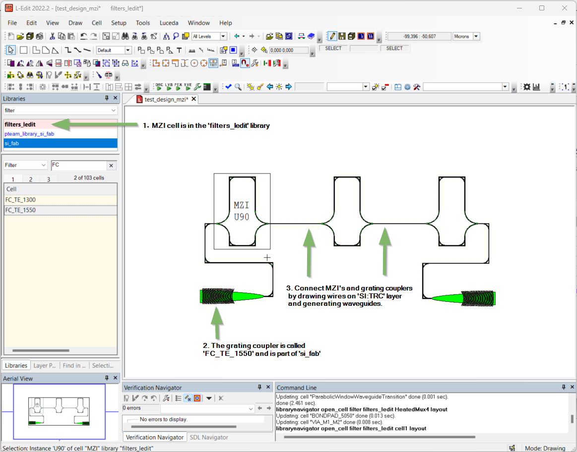
Create a design test_design_mzi, place three cascaded MZI components, two fiber grating couplers and draw the connecting wires.
The final result is shown below (Figure Final design).
Finish by generating the waveguides
Finished design after generating the waveguides.
Conclusion
In this short tutorial you learned how to create a cell in L-Edit, which can be reused in other designs. This method is very powerful because it allows cell reuse and allows to manage design complexity by splitting your design in smaller chunks that are easier to understand. Note that in this case, the created MZI is a fixed cell. If you want to make parametric cells, we suggest to have a look at IPKISS PCells.